® 724/725/726 Calibrators Calibration Manual PN 667581 September 1999 Rev. 3, 4/14 ©1999-2014 Fluke Corporation. All rights reserved. Printed in USA All product names are trademarks of their respective companies.
LIMITED WARRANTY AND LIMITATION OF LIABILITY Each Fluke product is warranted to be free from defects in material and workmanship under normal use and service. The warranty period is three years and begins on the date of shipment. Parts, product repairs, and services are warranted for 90 days.
Table of Contents Title Page Introduction........................................................................................................ 1 Contacting Fluke ................................................................................................ 1 Read First – Safety Information ......................................................................... 2 International Symbols ........................................................................................ 3 Specifications ............
724/725/726 Calibration Manual Lower Display Frequency Measurement Test (725 and 726) ....................... Lower Display Frequency Source Test (725 and 726) .................................. Lower Display 4-Wire Resistance Measurement Tests ................................. Lower Display 3-Wire RTD Measurement ................................................... Lower Display Thermocouple Measurement Tests ....................................... Lower Display Thermocouple Source Test ...................
List of Tables Table 1. 2. 3. 4. 5. 6. 7. 8. 9. 10. 11. 12. 13. 14. 15. 16. 17. 18. 19. Title International Symbols ............................................................................................ Upper Display Remote Commands (725 with V2.xx and lower) .......................... Lower Display Remote Commands (725) .............................................................. Remote Commands for Sensor Selection (725 with V2.xx and lower) ................. Serial Command List-726 and 725 V3.
724/725/726 Calibration Manual iv
List of Figures Figure 1. 2. 3. 4. 5. 6. 7. 8. 9. 10. 11. 12. 13. 14. 15. 16. 17. 18. 19. 20. 21. 22. 23. 24. 25. 26. 27. 28. 29. 30. 31. 32. 33. 34. 35. 36. Title Replacing the Batteries and Replaceable Fuses ..................................................... Upper Display Voltage Test Connections .............................................................. Lower Display mV and Voltage Test Connections ................................................ Upper Display mA Test Connections................
724/725/726 Calibration Manual vi
Introduction Warning The information provided in this manual is for the use of qualified personnel only. Do not perform the verification tests or calibration procedures described in this manual unless you are qualified to do so.
724/725/726 Calibration Manual Read First – Safety Information In this calibration manual, a Warning identifies conditions and actions that pose hazard(s) to the user. A Caution identifies conditions and actions that may damage the Calibrator or the test instruments. Warnings To avoid possible electric shock or personal injury: 2 • DO NOT use the Calibrator if it looks damaged. • Follow all safety procedures for the test and calibration equipment you use. • Examine the Calibrator before use.
Calibrators International Symbols Warnings (cont.) • When servicing the Calibrator, use only specified replacement parts. • To avoid false readings, which can lead to possible electric shock or personal injury, replace the batteries as soon as the low battery indicator () appears. Caution To avoid possible damage to the Calibrator or to the test instruments: • Disconnect the power and discharge all high voltage capacitors before testing resistance, diodes, or continuity.
724/725/726 Calibration Manual Specifications Performance and accuracy are specified for one year after calibration, at operating temperatures of +18 °C to +28 °C (64 °F to 82 °F), in relative humidity to 90 %, after a 5 minute warm up period. Note A “count” is the amount by which the least significant digit can vary. DC Voltage Measurement (724 and 725) Range Resolution Accuracy (% of Reading + Counts) 30 V (upper display) 0.001 V 0.02 % + 2 20 V (lower display) 0.001 V 0.
Calibrators Specifications DC mA Measurement and Source (726) Range Minimum Maximum Accuracy, (% of Reading + Floor) mA Read (Upper Display) 0.000 24.000 0.010 % + 2 μA mA Read (Lower Display) 0.000 24.000 0.010 % + 2 μA mA Source 0.000 24.000 0.010 % + 2 μA Maximum load on, mA source is 1 kΩ. With the HART resistor on, maximum load is 750 Ω.
724/725/726 Calibration Manual Ohms Source (726) Ohms Range Ohms Source (low) Ohms Source (high) Minimum Maximum Accuracy (% of Reading + Floor) Excitation Current from Measurement Device 5.0 400.0 0.1 mA to 0.5 mA 0.015 % + 0.1 Ω 5.0 400.0 0.5 mA to 3 mA 0.015 % + 0.05 Ω 400 1500 0.05 mA to 0.8 mA 0.015 % + 0.5 Ω 1500 4000 0.05 mA to 0.4 mA 0.015 % + 0.5 Ω Unit is compatible with smart transmitters and PLCs.
Calibrators Specifications Frequency Source (726) Range Minimum Maximum Accuracy CPM Source 2.0 1000 0.05 % Hz Source 1.0 1000.0 0.05 % 1.0 10.00 0.25 % 10.00 15.00 0.50 % kHz Source Millivolt Measurement and Source (724 and 725) Range* -10 mV to +75 mV Resolution Accuracy ±(0.025 % + 1 count) 0.01 mV Maximum input voltage: 30 V Temperature coefficient -10 °C to +18 °C, 28 °C to 55 °C: ±0.005 % of range per °C *Select this function by pressing .
724/725/726 Calibration Manual Temperature, Thermocouples (726) Type J K T E R S B C L U N XK BP Minimum Maximum (°C) (°C) CJC ON Accuracy (°C) -210 0.0 0.6 0.4 0.0 800 0.4 0.2 800 1200 0.5 0.3 -200 0.0 0.8 0.6 0.0 1000 0.5 0.3 1000 1372 0.7 0.5 -250 0.0 0.8 0.6 0.0 400 0.4 0.2 -250 -100 0.8 0.6 -100 1000 0.4 0.4 -20 0.0 2.0 1.8 0.0 1767 1.4 1.2 -20 0.0 2.0 1.8 0.0 1767 1.4 1.2 600 800 1.4 1.2 800 1000 1.5 1.3 1000 1820 1.7 1.
Calibrators Specifications Temperature, RTD Ranges, and Accuracies (724 and 725) Accuracy Type Range (°C) Measure 4-wire (°C) Measure* 2- and 3-wire (°C) Source (°C) -80 to 260 0.2 0.3 0.2 Pt100-385 - 200 to 800 0.33 0.5 0.33 Pt100-392 -200 to 630 0.3 0.5 0.3 Pt100-JIS -200 to 630 0.3 0.5 0.3 Pt200-385 -200 to 250 250 to 630 0.2 0.8 0.3 1.6 0.2 0.8 Pt500-385 -200 to 500 500 to 630 0.3 0.4 0.6 0.9 0.3 0.4 Pt1000-385 -200 to 100 100 to 630 0.2 0.2 0.4 0.5 0.2 0.
724/725/726 Calibration Manual RTD Accuracy (Read and Source) (ITS-90) (726) Range Ni120 (672) Pt100 (385) Pt100 (3926) Pt100 (3916) Pt200 (385) Pt500 (385) Pt1000 (385) CU10 Minimum Maximum Accuracy -80.00 °C 260.00 °C 0.15 -200.00 °C 100.00 °C 0.15 100.00 °C 300.00 °C 0.25 300.00 °C 600.00 °C 0.35 600.00 °C 800.00 °C 0.45 -200.00 °C 100.00 °C 0.15 100.00 °C 300.00 °C 0.25 300.00 °C 630.00 °C 0.35 -200.00 °C 100.00 °C 0.15 100.00 °C 300.00 °C 0.25 300.00 °C 630.
Calibrators Specifications Loop Power Supply Voltage: 24 V Maximum current: 22 mA Short circuit protected Pressure Measurement (725 and 726) Range Resolution Determined by pressure module 4 digits Accuracy Determined by pressure module Units psi, inH2O@4 °C, inH2O@20 °C, kPa, cmH2O@4 °C, cmH2O@20 °C, bar, mbar, kg/cm 2, mmHg, inHg Mode (726 Only) Pushing for 3 seconds stores present pressure value as an offset and subtracts it from the displayed value.
724/725/726 Calibration Manual General Specifications Operating temperature 724 and 725 726 -10 °C to 55 °C -10 °C to 50 °C Storage temperature - 20 °C to 70 °C (limited by battery storage specifications) Stability ± 0.
Calibrators Replacing the Batteries Replacing the Batteries Warning To avoid electric shock, remove the test leads from the Calibrator before opening the battery door. Close and latch the battery door before using the Calibrator. To avoid false readings, which can lead to possible electric shock or personal injury, replace the batteries as soon as the low battery indicator () appears. When replacing the batteries, always use four new AA batteries. Never mix new and used batteries in the Calibrator.
724/725/726 Calibration Manual Fuses Warning To avoid electrical shock: • Remove the test leads from the calibrator before opening the battery door. Close and latch the battery door before using the calibrator. • Use only the specified replacement fuses listed under “Replaceable Parts”. • Do not allow water into the case. Note 724 and 725 Version 2.x and lower. Over time, the input protection has been modified to increase reliability.
Calibrators Remote Control Interface (725 and 726) Remote Control Interface (725 and 726) The Calibrator’s serial interface and remote control commands let you use a PC to remotely select Calibrator functions and read the Calibrator’s display. This remote interface is especially useful if you want to write your own calibration software. The 726 and 725 with V3.0 and higher firmware remote control interface is always active. To activate the 725 with firmware V2.
724/725/726 Calibration Manual Table 2. Upper Display Remote Commands (725 with V2.xx and lower) Remote Command Description i mA measurement L mA Loop Power E Voltage measurement B Single broadcast of the most recent upper display value and units ( Single broadcast of most recent upper display value without header or units Table 3.
Calibrators Remote Control Interface (725 and 726) Table 4. Remote Commands for Sensor Selection (725 with V2.xx and lower) Selection Entry Serial Input No.
724/725/726 Calibration Manual Serial Command List (726) Table 5 lists the serial commands for the 726 and 725 Calibrator with V3.00 and higher firmware. Refer to “Remote Control Interface (725 and 726)” for activation steps. Table 5. Serial Command List-726 and 725 V3.
Calibrators Serial Command List (726) Table 5. Serial Command List-726 and 725 V3.00 and Later (cont.) Command Response/Actions OUT Command Arguments Comment Arguments: Configures {value} {units} the output Multipliers: source u for micro, m for function. If the milli, and k for kilo {value} and are accepted.
724/725/726 Calibration Manual Table 5. Serial Command List-726 and 725 V3.00 and Later (cont.) Command Response/Actions LOWER_MEAS Command Arguments Comment 1 argument, Valid Configures the Modes: measurement DCI, DCMV, DCV, function. Sets TC, RTD, the specified FREQUENCY, measure mode Ch 1 Ch 2 X PULSE_TRAIN SIM 1 Argument {value} If the value is Multipliers u for micro, valid, this m for milli, and k for command will kilo are accepted.
Calibrators Serial Command List (726) Table 5. Serial Command List-726 and 725 V3.00 and Later (cont.
724/725/726 Calibration Manual Table 5. Serial Command List-726 and 725 V3.00 and Later (cont.) Command CPRT_MAX_T? (726 only) Response/Actions Command Arguments Comment Returns {number} CEL. Ch 1 Ch 2 X 1 argument. Sets the CPRT_COEFA (726 only) custom CPRT X Coefficient A. CPRT_COEFA? (726 only) Returns the custom CPRT X Coefficient A. 1 argument. Sets the CPRT_COEFB (726 only) custom CPRT X Coefficient B. CPRT_COEFB? (726 only) Returns the custom CPRT X Coefficient B. 1 argument.
Calibrators Serial Command List (726) Table 5. Serial Command List-726 and 725 V3.00 and Later (cont.) Command Response/Actions Command Arguments Comment CUST3_ALIAS? (726 only) Returns screen name for CUST3 Verify RTD 3 RTD. alias HART_ON Turns HART mode on. Switches in 250 Ω resistor HART_OFF Turns HART mode off.
724/725/726 Calibration Manual Required Equipment Equipment and software required to perform the procedures in this manual are identified in Table 6. If the recommended equipment model is not available, other equipment can be substituted if it meets the specifications indicated. Warning To avoid safety hazards and equipment damage during the calibration procedures, use the specified calibration equipment listed in Table 6. Using unspecified equipment can give unreliable results and pose safety hazards.
Calibrators Performance Tests Performance Tests Warning Some of the performance tests involve the use of high voltages and should be performed by qualified personnel only. To avoid electric shock, always set the calibration source (5520A) to Standby (STBY) mode between tests and before handling the test connections or test cables. Performance tests confirm the complete operability of the Calibrator and check the accuracy of each function against the Calibrator’s specifications.
724/725/726 Calibration Manual Upper Display Voltage Measurement Tests 1. Press RESET on the 5520A. 2. Press on the UUT until V appears on the upper display. 3. Make the connections shown in Figure 2. 4. Set up the 5520A to output each of the voltages in Table 7 and verify that the UUT readings are within the limits shown. 5. Press STBY on the 5520A. aal03f.eps Figure 2. Upper Display Voltage Test Connections Table 7.
Calibrators Performance Tests Lower Display mV/TC Measurement Tests 1. Press RESET on the 5520A. 2. Press on the UUT until MEASURE and mV appear on the lower display. 3. Make the connections shown in Figure 3. 4. Set up the 5520A to output each of the voltages in Table 8 and verify that the UUT readings are within the limits shown. 5. Press STBY on the 5520A. aal04f.eps Figure 3. Lower Display mV and Voltage Test Connections Table 8.
724/725/726 Calibration Manual Lower Display Voltage Measurement Tests 1. Press RESET on the 5520A. 2. Press on the UUT until MEASURE and V appear on the lower display. 3. Make the connections shown in Figure 3. 4. Set up the 5520A to output each of the voltages in Table 9 and verify that the UUT readings are within the limits shown. 5. Press STBY on the 5520A. Table 9. Lower Display Voltage Readings 5520A Outputs 28 724/725 UTT Readings 726 UTT Readings 0.000 V -0.002 V to +0.002 V -0.002 V to +0.
Calibrators Performance Tests Upper Display mA Measurement Tests 1. Press RESET on the 5520A. 2. Press on the UUT until MEASURE and mA appear on the upper display. 3. Make the connections shown in Figure 4. 4. Set up the 5520A to output each of the voltages in Table 10 and verify that the UUT readings are within the limits shown. 5. Press STBY on the 5520A. aal05f.eps Figure 4. Upper Display mA Test Connections Table 10.
724/725/726 Calibration Manual Lower Display mA Measurement Tests (725 and 726) 1. Press RESET on the 5520A. 2. Press on the UUT until MEASURE and mA appear on the lower display. 3. Make the connections shown in Figure 5. 4. Set up the 5520A to output each of the voltages shown in Table 11 and verify that the UUT readings are within the limits shown. 5. Press STBY on the 5520A. aal06f.eps Figure 5. Lower Display mA Test Connections Table 11.
Calibrators Performance Tests Lower Display Frequency Measurement Test (725 and 726) 1. Set the 5520A to source a 10 kHz, 1 V peak-to-peak square wave (use the blue softkey under the wave type to change the wave shape). 2. Press on the UUT (for 726) until MEASURE and kHz appear on the lower display. 3. Make the connections shown in Figure 6. 4. Verify that the UUT frequency reads between 9.98 kHz and 10.02 kHz. 5. Press STBY on the 5520A. aal04f.eps Figure 6.
724/725/726 Calibration Manual Lower Display Frequency Source Test (725 and 726) 1. Press on the UUT until SOURCE appears on the lower display. 2. Press on the UUT (for 726) until Hz appears on the lower display. 3. Configure the Fluke 8508A to measure frequency; then make the connections shown in Figure 7. 4. Use the arrow keys on the UUT to set the UUT output 10 kHz at 5 V and verify that the Fluke 8508A readings are within the limits 9.975 Hz to 10.025 kHz. 5.
Calibrators Performance Tests Lower Display 4-Wire Resistance Measurement Tests 1. Press on the UUT (on 726) until Ω appears on the lower display. If necessary, use to get to the measure mode, and use )to get to the 4W mode. (MEASURE should also appear on the lower display). 2. Set the 5520A to 2-wire output with 2-wire compensation off; then make the connections shown in Figure 8. 3.
724/725/726 Calibration Manual Lower Display 3-Wire RTD Measurement 1. Press on the UUT (on the 726) until Ω appears on the lower display. If necessary, use to select the measure mode, and use (on the 726) to get to the 3W mode. (MEASURE should also appear on the lower display.) 2. Set the 5520A to 2-wire output with 2-wire compensation off; then make the connections shown in Figure 9. 3. Set the 5520A to source 350 Ω and verify that the UUT resistance readings are within the 349.80 to 350.2 Ω.
Calibrators Performance Tests Lower Display Thermocouple Measurement Tests 1. Remove the test leads from the UUT terminals; then connect a Type-J thermocouple lead between the TC jack on the UUT and the TC jack on the 5520A, as shown in Figure 10. 2. Press on the UUT until J appears on the lower display. If necessary, press (use the configuration menu on the 726) so the temperature is displayed in °C. 3.
724/725/726 Calibration Manual Lower Display Thermocouple Source Test 1. Set the 5520A to measure Type-J thermocouple voltages. 2. Press on the UUT until SOURCE appears on the lower display. If necessary, press on the UUT until J appears on the lower display and press (use the configuration menu on the 726) so the temperature is displayed in °C. 3. Use the arrow keys to set the UUT outputs to the temperatures in Table 14 and verify that the 5520A temperature readings are within the limits shown. 4.
Calibrators Performance Tests Lower Display mA Source Tests (725 and 726) 1. Press on the UUT until SOURCE appears on the lower display; then press until mA appears on the lower display. If necessary, press until SOURCE appears on the lower display. 2. Set the Fluke 8508A to measure dc current. 3. Connect the UUT and the Fluke 8508A as shown in Figure 11. 4. Use the arrow keys on the UUT to set the UUT to the currents in Table 15 and verify that the Fluke 8508A readings are within the limits shown.
724/725/726 Calibration Manual Lower Display mV Source Tests 1. Press on the UUT until SOURCE appears on the lower display; then press until mV appears on the lower display. 2. Set the Fluke 8508A to measure dc voltage in the 200 mV range. 3. Connect the UUT to the Fluke 8508A as shown in Figure 7. 4. Use the arrow keys on the UUT to set the UUT output to the current values in Table 16 and verify that the Fluke 8508A readings are within the limits shown. 5.
Calibrators Performance Tests Lower Display Ohms Source Tests 1. Press ( on the 726) on the UUT until Ω appears on the lower display. If necessary, press until SOURCE appears on the lower display. 2. Set the Fluke 8508A to measure 4-wire resistance. 3. Set the Fluke 8508A to 2 k range with LOI off for 72x resistance < 400 Ω, to 20 kΩ with LOI off range for 400 Ω or more. 4. Make the connections shown in Figure 12. 5.
724/725/726 Calibration Manual Pressure Module Input (725/726) 1. Connect a Fluke 700 Series Pressure Module to the 5-pin LEMO connector at the top of the UUT; then press . 2. Verify that the display first shows -----psi, then changes to a pressure value. 3. Disconnect the pressure module from the UUT. The performance tests for the 725 and 726 are now complete. Disconnect and secure all test equipment. Calibration Adjustment The Calibrators have electronic calibration.
Calibrators Calibration Adjustment To begin calibration, or to select a particular calibration step, type the cal step (letter or number), then press Enter on the PC keyboard. It is not necessary to run all of the calibration steps when in the calibration mode. However, for the 726, certain dependencies exist in that certain functions must be calibrated before others can be calibrated. These dependencies are related to calibration only.
724/725/726 Calibration Manual Initiating Communication (724 and 725 with V2.xx and Lower Firmware) Starting with the UUT off, push and hold while turning the UUT on. Continue to hold until "Cal mode" is displayed. “Enter Password:" appears on the display of all Calibrators that have firmware version V1.91 or higher. A password has been added to prevent users from accidentally changing the calibration of the Calibrator. The password for all 724 Calibrators is 427.
Calibrators Calibration Adjustment Calibration Adjustment Procedures (724 and 725 with V2.xx and Lower Firmware) The following sections detail the calibration procedures for the earlier 724 and 725 with V2.xx and lower firmware. Cal Volts Input Connect the UUT as shown in Figure 13. aal04f.eps Figure 13. Volts Input Calibration Connections From the Calibration Menu, type the cal step for Cal Volts Input.
724/725/726 Calibration Manual Cal Volts Output Connect the UUT as shown in Figure 14. aal08f.eps Figure 14. Volts Output Calibration Connections From the Calibration Menu, type the number or letter for Cal Volts Output. The PC displays: Zero into DAC. Enter the Volts displayed : Set the Fluke 8508A to read V DC. When the reading on the 8508A has stabilized, enter the value in volts on the PC, and press Enter.
Calibrators Calibration Adjustment Cal mA Input (Fluke 725 Only) Connect the UUT as shown in Figure 15. aal06f.eps Figure 15. mA Input Calibration Connections From the Calibration Menu, type the cal step for Cal mA Input. The PC displays: Enter 0 ma - press space bar to continue Set the Fluke 5520A to output 0.000 mA, let the reading settle a few seconds, then press the space bar on the PC.
724/725/726 Calibration Manual Cal mA Output (725 Only) Connect the UUT as shown in Figure 16. aal12f.eps Figure 16. mA Output Calibration Connections From the Calibration Menu, enter the cal step for Cal mA Output. The PC displays: Zero into DAC. Enter mA displayed : Set the Fluke 8508A to read DC current. When the reading on the Fluke 8508A has stabilized, enter the value in milliamps on the PC, then press Enter.
Calibrators Calibration Adjustment Cal mV Input Connect the UUT as shown in Figure 17. aal04.eps Figure 17. mV Input Calibration Connections From the Calibration Menu, type the number or letter for Cal mV Input. The PC displays: Enter 0 mV - press space bar to continue Set the Fluke 5520A to output 0.000 mV, let the output settle then press the space bar on the PC. After a short while, the PC displays the following calibration constant and new prompt: Offset = -714 Enter 90.
724/725/726 Calibration Manual Cal mV Output Connect the UUT as shown in Figure 18. aal08f.eps Figure 18. mV Output Calibration Connections From the Calibration Menu, enter the cal step for Cal mV Output. The PC displays: Zero into DAC. Enter mV displayed : Set the Fluke 8508A to read V DC. When the reading on the Fluke 8508A has stabilized, enter the value in millivolts on the PC, then press Enter. You only need to enter four places past the decimal point and do not need to enter the units (mV).
Calibrators Calibration Adjustment Cal Thermocouples Connect the UUT as shown in Figure 19. aal11f.eps Figure 19. Thermocouples Calibration Connections From the Calibration Menu, enter the cal step for Cal Thermocouples. The PC displays: Connect accurate T/C source : TYPE-J thermocouple Simulate 0.0 degrees C - press space bar to continue Set the Fluke 5520A to output 0.00 degrees C for a type-J thermocouple using the ITS90 standard, then press the space bar on the PC.
724/725/726 Calibration Manual Cal Ohms Hi Source Connect the UUT as shown in Figure 20. aal13f.eps Figure 20. Ohms Hi Source Calibration Connections From the Calibration Menu, enter the cal step for Cal Ohms Hi Source. The PC displays: 2500 into DAC. Enter Ohms displayed : Set the Fluke 8508A to read 4-terminal Ohms. Lock the 8508A 20 kΩ range with LOI off. When the reading on the Fluke 8508A has stabilized, enter the value in Ohms on the PC, then press Enter.
Calibrators Calibration Adjustment Cal Ohms Low Source The UUT connection is the same as cal Ohms Hi Source, it is shown in Figure 20. From the Calibration Menu, enter the cal step for Cal Ohms Low Source. The PC displays: 2500 into DAC. Enter Ohms displayed : Set the Fluke 8508A to read 4 terminal Ohms. Lock the 8508A 2 kΩ range with LOI off. When the reading on the Fluke 8508A has stabilized, enter the value in Ohms on the PC, then press Enter. After a short while, the PC displays: Max value into DAC.
724/725/726 Calibration Manual Cal RTD Low Range Connect the UUT as shown in Figure 21. aal09f.eps Figure 21. RTD Low Range Calibration Connections From the Calibration Menu, enter the cal step for Cal RTD Low Range. The PC displays: Apply 15 ohms to 4 wire jacks press space bar to continue Set the Fluke 5520A to output 15.00 Ohms, 2-wire output with 2-wire comp off, then press the space bar on the PC.
Calibrators Calibration Adjustment Cal RTD Hi Range The UUT connection is the same as Cal RTD Low Range, it is shown in Figure 21. From the Calibration Menu, enter the cal step for Cal RTD Hi Range. The PC displays: Apply 500 ohms to 4 wire jacks press space bar to continue Set the Fluke 5520A to output 500.0 Ohms, 2-wire output with 2-wire comp off, then press the space bar on the PC.
724/725/726 Calibration Manual Cal ISO Volts Connect the UUT as shown in Figure 22. aal03f.eps Figure 22. ISO Volts Calibration Connections From the Calibration Menu, enter the cal step for Cal ISO Volts. The PC displays: Enter 0 Volts - press space bar to continue Set the Fluke 5520A to output 0.0000 V, then press the space bar on the PC. After a short while the PC displays the following a calibration constant and new prompt: Offset = -324 Enter 30.
Calibrators Calibration Adjustment Cal ISO mA Connect the UUT as shown in Figure 23. aal05f.eps Figure 23. ISO mA Calibration Connections From the Calibration Menu, enter the cal step for Cal ISO mA. The PC displays: Enter 0 ma - press space bar to continue Set the Fluke 5520A to output 0.0000 mA. After a short while, the PC displays the following calibration constants and prompt: Offset = -323 Enter 24.00 ma - press space bar to continue Set the Fluke 5520A to output 24.
724/725/726 Calibration Manual Calibration Adjustment Procedures (726 and 724/725 with V3.00 and Higher) Note This procedure does not cover the verification of the unit. The Calibrator should never use up more than 50 % of its specifications immediately after calibration. When calibrating the 726, you can also exit and enter calibration mode while performing the verification, subject to the dependencies listed in the procedure.
Calibrators Calibration Adjustment 725 Calibration Menu Calibration Menu 1: ISO mA Input 2: ISO Volts Input 3: mA Input 4: mA Output 5: Volts Input 6: Volts Output 7: Low Ohms Source 8: High Ohms Source 9: Ohms Measure 10: TC mV Output 11: TC mV Input 12: TC CJC 13: Exit Enter Selection: 724 Calibration Menu Calibration Menu 1: ISO mA Input 2: ISO Volts Input 3: Volts Input 4: Volts Output 5: Low Ohms Source 6: High Ohms Source 7: Ohms Measure 8: TC mV Output 9:
724/725/726 Calibration Manual Calibrating Isolated mA Input Connect the UUT as shown in Figure 24. aal05f.eps Figure 24. Isolated mA Input Calibration Connections After the proper connections have been made, type “1” (the first calibration step) then press the Enter key on the PC keyboard. Input directions are displayed at the bottom of the calibration menu: Enter Selection: Input 0 mA, Press Enter When Stable Input 24 mA, Press Enter When Stable Use the 5520A to input 0 mA and then 24 mA.
Calibrators Calibration Adjustment Calibrating Isolated Voltage Input Connect the UUT as shown in Figure 25. aal03f.eps Figure 25. Isolated Voltage Input Calibration Connections After making the proper connections, type “2” then press the Enter key on the PC keyboard. Input directions are displayed at the bottom of the calibration menu: Enter Selection: Input 0 Volts, Press Enter When Stable Input 30 Volts, Press Enter When Stable Use the 5520A to input 0 V and then 30 V.
724/725/726 Calibration Manual Calibrating mA Input (Fluke 725 and 726 only) Connect the UUT as shown in Figure 26. aal06f.eps Figure 26. mA Input Calibration Connections After making the proper connections, type “3” then press the Enter key on the PC keyboard. Input directions are displayed at the bottom of the calibration menu: Enter Selection: Input 0 mA, Press Enter When Stable Input 24 mA, Press Enter When Stable Use the 5520A to input 0 mA and then 24 mA.
Calibrators Calibration Adjustment Calibrating mA Output (Fluke 725 and 726 only) Connect the UUT as shown in Figure 27. aal12f.eps Figure 27. mA Output Calibration Connections After making the proper connections, type “4” then press the Enter key on the PC keyboard. Input directions are displayed at the bottom of the calibration menu: Enter Selection: First Calibration Point. Enter mA displayed: Second Calibration Point. Enter mA displayed: Use the 8508A to measure the two calibration points.
724/725/726 Calibration Manual Calibrating Voltage Input Connect the UUT as shown in Figure 28. aal04.eps Figure 28. Voltage Input Calibration Connections After making the proper connections, type “5” for 726/725 or “3” for 724, and then press the Enter key on the PC keyboard. Input directions are displayed at the bottom of the calibration menu: Enter Selection: Input 0 Volts, Press Enter When Stable Input 20 Volts, Press Enter When Stable Use the 5520A to input 0 V and then 20 V.
Calibrators Calibration Adjustment Calibrating Voltage Output Connect the UUT as shown in Figure 29. aal08f.eps Figure 29. Voltage Output Calibration Connections After making the proper connections, type “6” for 726/725 or “4” for 724, and then press the Enter key on the PC keyboard. Input directions are displayed at the bottom of the calibration menu: Enter Selection: First Calibration Point. Enter Volts displayed: Second Calibration Point.
4/725/726 Calibration Manual Calibrating Low Ohms Source Connect the UUT as shown in Figure 30. aal13f.eps Figure 30. Low Ohms Source Calibration Connections After making the proper connections, type “7” for 726/725 or “5” for 724, and then press the Enter key on the PC keyboard. Input directions are displayed at the bottom of the calibration menu: Enter Selection: First Calibration Point. Enter Ohms displayed: Second Calibration Point.
Calibrators Calibration Adjustment Calibrating High Ohms Source Connect the UUT as shown in Figure 31. aal13f.eps Figure 31. High Ohms Source Calibration Connections After making the proper connections, type “8” then press the Enter key on the PC keyboard. Input directions are displayed at the bottom of the calibration menu: Enter Selection: First Calibration Point. Enter Ohms displayed: Second Calibration Point. Enter Ohms displayed The 8508A should be locked in the 20 kΩ range (0.1 mA excitation).
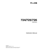
724/725/726 Calibration Manual Calibrating Ohms Measure Connect the UUT as shown in Figure 32. aal09f.eps Figure 32. Ohms Measure Calibration Connections After making the proper connections, type “9” for 726/725 or “6” for 724, and then press the Enter key on the PC keyboard.
Calibrators Calibration Adjustment Calibrating Thermocouple mV Output Connect the UUT as shown in Figure 33. aal08f.eps Figure 33. Thermocouple mV Output Calibration Connections After making the proper connections, type “10” for 726/725 or “8” for 724, and then press the Enter key on the PC keyboard. Input directions are displayed at the bottom of the calibration menu: Enter Selection: First Calibration Point. Enter mV displayed: Second Calibration Point.
724/725/726 Calibration Manual Calibrating Thermocouple mV Input Connect the UUT as shown in Figure 34. aal04f.eps Figure 34. Thermocouple mV Input Calibration Connections After making the proper connections, type “11” for 726/725 or “9” for 724, and then press the Enter key on the PC keyboard. Input directions are displayed at the bottom of the calibration menu: Enter Selection: Input –10mV, Press Enter When Stable Input 90mV, Press Enter When Stable Use the 5520A to input –10 mV and then 90 mV.
Calibrators Calibration Adjustment Calibrating Thermocouple CJC: Connect the UUT as shown in Figure 35. For the lag bath setup, see Figure 36. aal11f.eps Figure 35. Thermocouple CJC Calibration Connections The calibration of the TC CJC (Cold Junction Compensation) is a critical part of the calibration process, it is important that the thermocouple junction be allowed to completely stabilize. Usually this takes a minimum of five minutes.
724/725/726 Calibration Manual Replaceable Parts When servicing this Calibrator, use only the replacement parts specified. Userreplaceable parts are listed in Table 19 and shown in Figure 36. Table 19. Replacement Parts Item Fluke No. Quantity 724-725 Case top 726 Case top 664232 2491880 1 724 LCD mask 725 LCD mask 726 LCD mask 724 LCD mask for new LCD (FW rev 3.00+) 725 LCD mask for new LCD (FW rev 3.00+) 726 LCD mask for new LCD (FW rev 3.
Calibrators Replaceable Parts Table 19. Replacement Parts (cont.) Item Description Not Shown Fluke No. Quantity 724 Product Overview Manual 1547851 1 725 Product Overview Manual 1549644 1 726 Product Overview Manual 2441588 1 724 CD-ROM (contains Users Manual) 1547849 1 725/726 CD-ROM (contains Users Manual) 1549615 1 700SC serial interface cable 667425 Optional accessory [1] See www.fluke.com for more information about the test leads and alligator clips for your region.
724/725/726 Calibration Manual 72