
Application Note

Fluke Corporation 750 Series Documenting Process Calibrators 3
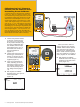
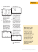
1. Make the RTD source
connections, S1, S2, S3 and
S4 (omit S3 and S4 for 2 wire
RTDs and S4 for 3 wire RTDs;
S4 is only needed for 4 wire
RTD sourcing).
2. Next, connect the loop power
and current measurement
connections, C1 and C2.
3. Once the connections are
made as per the diagram in
Figure 11, enable the loop
24 volt power from the setup
screen, source the pertinent
RTD for the specific transmit-
ter being evaluated, and set
the measure mode to mA.
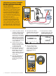
Figure 11.
3 and 4 Wire RTD Sourcing for the Fluke 750 Series
Documenting Process Calibrators
One of the most frequently asked application questions pertaining to
the 750 Series Documenting Process Calibrators is, “How do I hook
up the test leads to the DPC to source 3 and 4 wire RTDs?” For 3 and
4 wire RTD measurement, the DPC has embedded hookup diagrams
that easily show you how to connect the DPC. However, for 3 and 4
wire RTD source, the DPC does not offer that assistance.
The example shown below (Figure 11) depicts the hookup for a 3
and 4 wire Rosemount 444 RTD Transmitter. You will need an addi-
tional pair of TL22 test leads and AC20 industrial test clips to complete
all the connections necessary for this application. In order to double
the available connections to the source terminals on the DPC, you also
will need to utilize the short black jumpers supplied with the Docu-
menting Process Calibrator.
754
DOCUMENTING PROCESS CALIBRATOR
TEST DC PWR
++
––
Fluke DPC
C-2
C-1
S-3
S-2
S-4
S-1
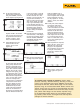
4. At this point, enter the split
screen mode of the DPC and
perform the As Found, Adjust
and As Left tests as you did
in the previous thermocouple
transmitter example.