
Application Note
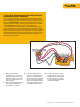
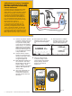

1. Connect the pressure module
to the DPC. Connect the out-
put of the I to P to the input
of the pressure module. If you
are using a differential pres-
sure module, make sure (for
this example) that it is a 15
PSI module and connect to
the input labeled “H”
(Figure 12).
2. Connect from the center two
banana type connections of
the DPC to the input of the I
to P where control current is
supplied (Figure 12).
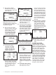
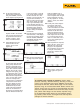
3. Once your connections are
made, assuming you are in
the power up state (or mea-
sure screen), select the “Pres-
sure” button (directly above
the “Range” button) (Figure
13).
4. Next depress the “MEAS/
SOURCE” button; now you are
in the source screen
(Figure 14).
Figure 14.
4 Fluke Corporation 750 Series Documenting Process Calibrators
754
DOCUMENTING PROCESS CALIBRATOR
Pressure Button
Figure 13.
+
754
DOCUMENTING PROCESS CALIBRATOR
Pressure
Module
Figure 12.
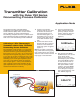
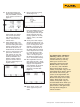
Calibration of an I to P (Current to
Pressure) with the Fluke 750 Series
Documenting Process Calibrators
A common device in the Fluke DPC workload
is the I to P. The I to P device is used to con-
vert electrical loop analog control of 4-20 mA
to pneumatic analog loop control of 3-15 PSI.
The device in this example is an I to P with
current input values of 4-20 mA for 0 % and
100 % with output range of 3-15 PSI for 0 %
and 100 %, +/- 2 %. This step-by-step exam-
ple describes how to: 1) perform a three point
ascending (3↑) As Found (pre-adjustment) test
at 0-50-100 %, Tag the results, 2) Adjust the
zero and span (span = 100 %) of the I to P,
then 3) perform a three point ascending As
Left (post-adjustment) test at 0-50-100 %, Tag
those results and review them in memory.
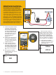
Since you want to source a
current, depress “mA.” Depress
“ENTER” which chooses “Source
mA” when given the choice of
“Source mA” or “Simulate Trans-
mitter.” When the DPC responds
with ????? asking for a current to
source, depress “4” and “ENTER.”
5. Next depress the “MEAS/
SOURCE” button once and you
should be in the split screen
mode (Figure 15).
Figure 15.