
Application Note
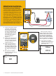
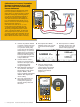

1. Connect the pressure module
to the DPC. Connect the input
of the P to I and the output
of a pressure hand pump
to the input of the pressure
module using a “T” connector
(Figure 20). If you are using a
differential pressure module,
ensure (for this example) it is
a 15 PSI module and connect
to input labeled “H.”
2. Connect from the center 2
banana type connections of
the DPC to the input of the P
to I where loop power
is supplied (Figure 20).
3. Next, depress the “SETUP” but-
ton on the DPC. The cursor
should begin on loop power.
Depress “ENTER,” down
arrow to Enabled and depress
“ENTER.” Next depress the
“Done” softkey.
4. Once your connections are
made, assuming you are
in the power up state (or
measure screen), select the
mA button.
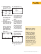
5. Next depress the “MEAS/
SOURCE” button; now you are
in the source screen (Figure
21).
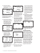
Figure 21.
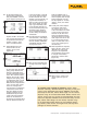
6. Since we wish to source
a pressure (using a hand
pump) depress the pressure
button, (directly above the
HART or range button)
(Figure 22).
6 Fluke Corporation 750 Series Documenting Process Calibrators
7. Next depress the “MEAS/
SOURCE” button once and
you should be in the split
screen mode (Figure 23).
Figure 23.
+
754
DOCUMENTING PROCESS CALIBRATOR
Hand Pump
Pressure
Module
Figure 20.
754
DOCUMENTING PROCESS CALIBRATOR
Pressure Button
Figure 22.
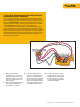
Calibration of a Pressure Transmitter
(Pressure to Current or P to I) with
the Fluke 750 Series Documenting
Process Calibrators
A common device in the Fluke DPC work-
load is the pressure transmitter or P to I
device. The P to I device is used to convert
pneumatic analog loop control signals of
3-15 PSI or other measured pressures to
electrical loop analog control signals of
4-20 mA. The device in this example is a
P to I with pressure input values of 3-15
PSI for 0 % and 100 % with output range
(drawn from loop power) of
4-20 mA for 0 % and 100 %, +/- 2 %.
In this step-by-step example we will:
1) perform a three point ascending (3↑)
As Found (pre-adjustment) test at 0-50-
100 %, and Tag the results, 2) adjust the
zero and span (100 %) of the P to I, then
3) perform a three point ascending As Left
(post-adjustment) test at 0-50-100 %, tag
those results and review them in memory.