
Application Note


Eliminating sensor
errors in loop
calibrations
Calibrating a loop is more than just
4 mA to 20 mA
Significant performance
improvement can realized by
optimizing the loop calibration
measurement system to better
accommodate the unique char-
acteristics of the temperature
sensing element. All tempera-
ture probes and their sensing
elements are unique, with
variations in materials, con-
struction and usage, or exposure
to different environments. This
uniqueness continues through-
out the useful life of the sensor,
in the form of drift due to
mechanical shock and vibra-
tion or to contamination of the
materials when exposed to the
material they are measuring.
Only through periodic verifica-
tion can these differences and
changes be accommodated,
improving total measurement
performance.
Temperature plays an impor-
tant role in many industrial and
commercial processes. Examples
range from sterilization in
pharmaceutical companies,
metal heat-treatment to ensure
optimal strength in aerospace
applications, temperature
verification in a cold storage
warehouse, and atmospheric
and oceanographic research. In
all temperature measurement
applications, the sensor strongly
affects the results; unfortu-
nately, many measurements are
made without optimizing the
system to get the best perfor-
mance from the temperature
transducer.
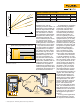
The majority of process
temperature measurements are
performed using a sensing ele-
ment connected to a transmitter.
Figure 1 shows a diagram of a
common configuration.
In many applications, it is
common to verify the elements
of the measurement system
separately, but in doing so,
significant improvements made
possible by considering the
system as a whole are ignored.
One of the main reasons the
elements are verified or cali-
brated separately is that it is
often considered to be more
efficient. Verifying the mea-
surement component is done
simply and quickly with an
electronic thermocouple (TC) or
resistance temperature detector
(RTD) simulator. This approach
does not verify the performance
of the associated temperature
probe, and assumes all probes
are identical and closely follow
some standard. In practice, no
two probes are identical; they
all vary from the ideal standard,
and over time and usage their
characteristics change. Under-
standing how probes vary from
the ideal will allow you to opti-
mize the measurement system
to achieve the best performance.
Figure 1. Diagram of a typical process temperature measurement system.
Application Note
From the Fluke Calibration Digital Library @ www.flukecal.com/library