
Application Note

Application Note
Pressure switches are used in a
wide variety of monitoring and
control applications, such as
HVAC air provers, defrost sensors,
filter indicator applications, oil/
hydraulic filter alerts and process
break detectors.
A pressure switch is triggered
by changes in pressure within a
system, which can be measured
as pressure, vacuum, or differen-
tial
between two pressure inputs.
In every case, the pressure switch
will employ a diaphragm, piston,
or other pressure-responsive
sensor coupled to a switch actu-
ating mechanism.
In its most basic form, a pres-
sure switch can monitor air flow
in a heating system or control gas
pressure in a water heater, acting
as the watchdog in many process
monitoring applications.
Accurate calibration of pres-
sure switches is a critical step
in ensuring process quality and
the safe operation of equip-
ment. But even the most savvy
process technician may not fully
understand the correct method
of calibrating pressure switches.
Fortunately, the best tool for
the job is one many process
technicians already own: a docu-
menting process calibrator, like
the Fluke 750 Series.
Documenting process calibra-
tors (DPCs) are multifunction
process tools that eliminate the
need for technicians to carry mul-
tiple tools with them. “The 754
Documenting Process Calibrator
has literally saved me a zillion
steps,” said Gene Guidry, Chevron
Chemical, U.S.A. “I was carry-
ing two, three, maybe even four
pieces of test equipment plus my
hand tools. Now I just take the
754, which incorporates calibra-
tion and HART communication
capability in a single, fast unit.”
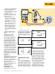
Calibrating a pressure switch
using a DPC can be conducted
manually or as an embedded
task using DPC software. It also
requires certain pressure accesso-
ries, including a pressure module
and hand pump. The steps
outlined below are specific to the
Fluke 750 Series, but the process
can be applied to virtually any
DPC.
Calibrating pressure
limit switches
The first step in the process is to
set up the DPC. (Note: A number
of the terms in this article apply
to both temperature and pres-
sure limit switch calibration and
maintenance.)
The DPC test setup screens
prompt the user for the following
information:
• Setpoint: Main point at which
the switch is supposed to take
action.
• Setpoint type: Can be “high”
or “low.” This is the basic call
to action. “Low” means that
the action should happen
when the process variable (PV)
is below the setpoint. “High”
means that the action should
happen if the PV is above the
setpoint.
• Set state: State of the switch
(set or reset) at the time the
action takes place.
• Tolerance: The allowable
deviation from the setpoint.
• Deadband min: Minimum
value or size of the deadband.
Calibrating pressure
switches with a DPC
• Deadband max: Maximum
value or size of the deadband.
(note: the deadband of a
pressure switch is the mea-
sured difference in the applied
pressure when the switch is
changed from set to reset)
• Trip function: This can be set
for continuity, V ac or V dc,
and refers to what is being
measured as the setpoint is
exercised by the simulated
process variable.
For example, suppose you
want to control the pressure in
a vessel set at 12 psi. You don’t
want the relief valve to be open-
ing and closing constantly, you
want it to open at 12 psi and
close again at approximately
10 psi, (12 psi - 10 psi = an
approximate deadband of 2 psi).
From the Fluke Digital Library @ www.fluke.com/library