
Application Note

Application Note
Process switches
A process switch is a device that
can sense a process variable —
such as temperature or pressure
— and change the state of one or
more sets of switch contacts
when that variable reaches a
predetermined value. This value
is called a setpoint. A switch can
have multiple setpoints. Let’s look
at some important c
onc
epts of
how proc
ess switches work.
Contacts. Contacts come in
pairs, and a pair is either nor
-
mally open or normally closed.
“Normally” means without ener-
g
ization — just the way the
contacts would be on the shelf or
if you disconnected the power
w
ires from the switch.
Many process switches have
four sets of contacts — two
normally open and two normally
closed. But, there are many
variations. A single switch may
operate just one set of contacts,
or it may operate multiple sets
Process and temperature
switch applications with
the 740 Series DPCs
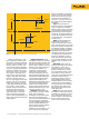
What about actuation? You
might want the switch to failsafe
upon loss of level in a cooling
tank. So, normal level would acti-
vate the switch (compared to its
shelf position). Upon loss of level,
the switch deactivate — that is, it
will assume the same state that
it would be in if it were on the
shelf. For an example of this
control logic, look at a typical
toggle-style light switch. You will
notice the word “ON” under the
toggle handle and the word OFF
above it. To reveal the word “ON,”
you must flip the switch up. If the
toggle mechanism were to fail
mechanically — which could
happen if, for example, it were to
melt due to arcing — the toggle
handle would drop into the “OFF”
position due to gravity. That is the
failsafe position of these switches.
It’s common to implement process
switches the same way.
Setpoint. A switch may have
multiple setpoints
. For example,
many level switches come with
low-low, low, high, and high-
high sets of contacts — each with
its own setpoint.
But, it can get more c
omplex
than that, depending on the
required control scheme and the
type of sw
itch used. There are
many ways to accommodate
complex switching schemes —
including the use of an analog
transmitter serves as the input to
a virtual switch (implemented in
software).
From the Fluke Digital Library @ www.fluke.com/library
of normally open and normally
closed contacts. You select which
contacts to use based on the
desired output for a given condi-
tion and a given failsafe condition.
Control logic. You must think
of switch actuation and contact
state separately. Actuating the
typical process switch means
opening one set of contacts and
closing another at the same time.
Whether actuation opens or
closes a set of contacts depends
on whether you are using the
normally open or normally closed
contacts and whether the switch
is in an activated or deactivated
state during normal operation.
Failsafe operation is the first
criterion to assess when deciding
which set of contacts to use. For
example, you should use normally
closed contacts if breaking the
circuit will result in a failsafe
condition. Because loss of power
and an open circuit (via a broken
circuit wire, broken connection,
or intentional operation) have the
same effect on circuit operation,
the normally open contacts would
b
e the c
orrect ones to use. Upon
loss of power, these contacts
will open. So, you would want
them to b
e closed for normal
operations and to open when
operations go into alarm or
c
ontrol change c
onditions
.
It is not true that, for example,
a high level sw
itch w
ill nec
essar
-
ily close c
ontacts when you reach
a high level condition. Good con-
trol practic
es usually dictate the
opposite.
This note discusses appli-
cations for process
switches and calibrating
temperature switches
using the Fluke 740 Series
Documenting Process
Calibrators (DPCs). Let’s
begin by looking at what a
process switch is and
what it does.