
Application Note

When you calibrate a high level
switch, you do so with the level
rising. This is standard practice
with all process variables, not
just level — you get a more accu-
rate calibration by accounting for
hysteresis.
Trip. This is the value at
which the switch will change the
state of a given set of contacts.
Where a switch trips is a function
of its setpoint and direction. For a
pressure switch with a setpoint
of 500 PSI, the switch should trip
at 500 PSI as pressure rises. Trip
is also called “set.” The opposite
of that is reset
.
Reset. Some switches reset
automatically, while others
require a manual reset
. In either
case, the reset will not occur until
the switch actuator has moved in
the direction opposite its trigger-
ing direction enough to overcome
hysteresis (and/or deadband —
see below) and allow the switch
to change contact states back to
normal. An exception to this is
when the switch is used to indi-
cate a normal condition. For such
switches, reset is usually not an
issue.
Hysteresis. This is the ten-
dency of the switch to stay in the
last position it was in. This
means that when you are cali-
brating a switch to trip at 500
PSI, the hysteresis of the switch
may cause it to trip at 501 PSI
when you are increasing pressure
and 499 PS
I when you are
decreasing pressure. If this is a
high pressure sw
itch (c
ontrol
function requires a trip on rising
pressure), you would calibrate it
to trip at 500 PS
I on an increas
-
ing pressure input and let the
498 PSI trip serve as the maxi-
mum reset value.
Band
.
This is the area around
the setpoint where the switch is
c
ontrolling the proc
ess
. F
or exam
-
ple, if the sw
itch will control a
tank to maintain a level between
6 feet of water and 9 feet of
water, it has a band of 3 feet
.
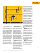
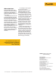
Deadband
Open
High Limit
Process
Variable
Low Limit
Setpoint
Reset
Closed
50
°C
20 °C
Deadband
Closed
Reset
Setpoint
Open
Figure 1. 2-point switch with settings for low and high setpoints.
2 Fluke Corporation Process and temperature switch applications with the 740 Series DPCs
Here’s an example of a com-
plex application. A level switch
may allow a “normal” indication
(such as a light) to display at any
level up to 82 %. At 82 %, the
switch causes normal indication
to go off — placing the indication
between a normal state and an
alarm state. At 85 %, the switch
ma
y trigger a high level alarm
light. At 90 %, the switch may
trigger a high-high level alarm
light plus an audio alarm
. A
t
93 %, it ma
y trigger a feed valve
closure. At 95 %, it may trigger
dump valve operation
. A
t 9
7 %,
it ma
y trigger drain pump opera
-
tion. At 98 %, it may actuate
isolation doors in the room c
on
-
taining the tank
. And those
actions are just for high level.
This same sw
itch, or another,
might c
ontrol low level opera-
tions. In some configurations, you
might ha
ve separate sw
itches for
each setpoint
.
Setpoint tolerance. This is
the amount of error you can have
between the desired setpoint and
the one you actually set. It’s not
always easy to calibrate a switch
directly on the desired setpoint —
for a variety of reasons. For
example, if you must open a
valve when the temperature
reaches 3
1
3 deg
rees, your set
-
point tolerance might allow you
consider the switch calibrated if
it trips w
ithin 5 deg
rees of the
setpoint
. T
olerances may be
expressed in engineering units or
in perc
ent
. When expressed in
perc
ent, that normally means
percent of the control
band (we
explain band b
elow), not in per
-
c
ent of the setpoint value.
Direction. Switch actuation
(and, therefore, c
ontrol) is direc
-
tional, due to hysteresis
.
Sometimes, the hysteresis value
can exc
eed the setpoint toler
-
anc
e. For non-critical applications
with wide setpoint tolerances,
you can probably ig
nore hystere
-
sis
. But, standard practice is to
observe direction when calibrat-
ing a setpoint
. When you
calibrate a low level switch, you
do so with the level dropping.