
Application Note

Application Note
From the Fluke Digital Library @ www.fluke.com/library
Remote programming
and measuring
uncommon RTDs with
the Fluke 726
Using custom RTD temperature constants
The Fluke 726 Multifunction Process Calibrator can
measure temperature with most common resistance
temperature detectors (RTD’s). But what about the many
“legacy” non-standard RTD’s still in use, as well as standard
RTDs that have been specially calibrated? The 726 allows
you to enter custom RTD constants so you can measure
any RTD for which you have the constants. You can also
use custom constants to take advantage of the Fluke 726
ability to measure with 0.01° resolutions by coupling it with
a characterized RTD. This application note explains how
to use the 726 to measure non-standard or characterized
RTD’s. It covers the basic theory of RTD conversion formu-
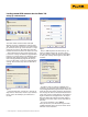
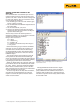
las and shows how to load custom constants into the Fluke
726 using a Windows PC with an RS-232 serial port.
RTD Temperature Curves
RTD’s take advantage of a natural property of
metals, namely that a metal’s resistance increases
with temperature. An RTD is a precisely manu-
factured metal wire or film, and by measuring its
resistance we can derive its temperature.
Resistance of an RTD is a function of the length
and cross sectional area of the wire or film used to
make it, and the resistivity of its metal. Resistivity
is a characteristic of a metal’s chemical makeup.
Most RTD’s are made of platinum, nickel, or copper.
The alloy of the platinum or copper must be tightly
controlled to produce precise resistivity. Interna-
tional standards like IEC 60751 and ASTM 1137
define the geometry and resistivity of standard
RTD’s. RTD manufacturers work to build their prod-
uct to meet these standards.
In addition to defining the physical parameters of
standard RTD’s, international standards also define
equations and constants used to convert resistance
readings to temperature. Over a limited range the
relationship between temperature and resistance is
approximately linear, and you can convert tempera-
ture to resistance using Equation 1.
Equation 1: R
t
= R
0
(1 + at)
Where: t is the temperature of the sensor
R
0
is the resistance at 0 °C.
a is a constant slope that describes
resistance change per degree C.
R
t
is the resistance at temperature t,
in degrees C.
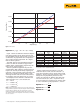
Using this simple linear equation delivers fairly
good results, especially at temperatures between 0
and 100 °C. To extend the range of the RTD and to
get more precision, IEC and ASTM standards specify
a more complex polynomial that fine-tunes the
resistance-temperature relationship. One form of
that equation is given here as Equation 2. The RTD
standards also specify values for the constants R
0
,
A, B, C. (The C constant is only used for tempera-
tures less than 0 °C.)