789 ProcessMeter™ Calibration Manual September 2002, Rev.1, 3/13 © 2002-2013 Fluke Corporation. All rights reserved. Specifications are subject to change without notice. All product names are trademarks of their respective companies.
LIMITED WARRANTY AND LIMITATION OF LIABILITY Each Fluke product is warranted to be free from defects in material and workmanship under normal use and service. The warranty period is three years and begins on the date of shipment. Parts, product repairs, and services are warranted for 90 days.
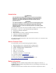
Table of Contents Title Page Introduction ........................................................................................................ How to Contact Fluke ........................................................................................ Safety Information ............................................................................................. Symbols ............................................................................................................. Specifications .......
789 Calibration Manual ii
List of Tables Table 1. 2. 3. 4. 5. 6. 7. 8. 9. 10. 11. 12. 13. Title Page International Symbols ............................................................................................ Required Equipment and Software ........................................................................ Typical Alkaline Battery Life ................................................................................ Current Sourcing Test ................................................................................
789 Calibration Manual iv
List of Figures Figure 1. 2. 3. 4. 5. 6. 7. 8. 9. 10. 11. 12. Title Page Replacing the Batteries and Fuses .......................................................................... Verifying Loop Power............................................................................................ Current Sourcing Connections Using the HP 3458A ............................................. Current Measurement Test Connections ................................................................
789 Calibration Manual vi
Introduction Warning The information provided in this manual is for the use of qualified personnel only. Do not perform the calibration verification tests or calibration procedures described in this manual unless you are qualified to do so. Caution The 789 ProcessMeter™ contains parts that can be damaged by static discharge. No procedure in this document requires the case to be opened. If you do so, follow the standard practices for handling static sensitive devices.
789 Calibration Manual Warning To prevent possible electrical shock, fire, or personal injury: • Read “Safety Information” before using the meter. • Do not use the meter if it is damaged. Before using the meter, inspect the case. Look for cracks or missing plastic. Pay particular attention to the insulation surrounding the connectors. • Make sure the battery door is closed and latched before operating the meter. • Remove test leads from the meter before opening the battery door.
ProcessMeter™ Symbols Symbols Symbols used on the ProcessMeter and in this calibration manual are explained in Table 1. Table 1. International Symbols Symbol Meaning Symbol Meaning Risk of danger. Important information. See Manual.
789 Calibration Manual Specifications All specifications apply from +18 °C to +28 °C unless stated otherwise. All specifications assume a 5-minute warm-up period. The standard specification interval is 1 year. Note “Counts” refers to the number of increments or decrements of the least significant digit. DC Volts Measurement Range (V dc) Accuracy, ±(% of Reading + Counts) Resolution 4.000 0.001 V 0.1 % + 1 40.00 0.01 V 0.1 % + 1 400.0 0.1 V 0.1 % + 1 1000 1V 0.
ProcessMeter™ Specifications AC Current Measurement Range 45 Hz to 2 kHz 1.000 A (Note) Resolution Accuracy, ±(% of Reading + Counts) 0.001 A 1%+2 Typical Burden Voltage 1.5 V/A Note: 440 mA continuous, 1 A 30 seconds maximum Specifications are valid from 5 % to 100 % of amplitude range. AC conversion: true rms Maximum crest factor: 3 (between 50 and 60 Hz) For non-sinusoidal waveforms, add ±( 2 % reading + 2 % f.s.
789 Calibration Manual Frequency Counter Sensitivity Minimum Sensitivity (rms Sinewave) 5 Hz to 5 kHz* Input Range AC DC (approximate trigger level 5 % of full scale) 400 mV 150 mV (50 Hz to 5 kHz) 150 mV 4V 1V 1V 40 V 4V 4V 400 V 40 V 40 V 1000 V 400 V 400 V *Usable 0.5 Hz to 20 kHz with reduced sensitivity. 106 VHz max Diode Test and Continuity Test Diode test indication: Displays voltage drop across device, 2.0 V full scale. Nominal test current 0.2 mA at 0.6 V.
ProcessMeter™ Required Equipment General Specifications Maximum voltage applied between any jack and earth ground ..................... 1000 V Battery Type ............................................ 1.5 V, 0-15 mA, AA, Alkaline Storage temperature .............................. -40 °C to 60 °C Operating temperature ........................... -20 °C to 55 °C Operating altitude ................................... 2000 meters maximum Frequency Overload Protection ............
789 Calibration Manual Table 2. Required Equipment and Software Equipment Minimum Specifications Recommended Model Calibration Source No Substitute Fluke Model 5500A Digital Process Meter or Digital Process Calibrator No Substitute Fluke 787 ProcessMeter Digital Multimeter No Substitute Agilent 3458A Test Leads, low leakage, RG-58/U type Leakage resistance > than 1.
ProcessMeter™ Basic Maintenance F1 F2 anw037.eps Figure 1. Replacing the Batteries and Fuses Battery Life Warning To avoid false readings, which can lead to possible electric shock or personal injury, replace the batteries as soon as the low battery indicator () appears. The ProcessMeter is powered by four AA alkaline batteries. Table 3 shows typical alkaline battery life. To preserve battery life: • Use current simulation instead of sourcing when possible. • Avoid using the backlight.
789 Calibration Manual Checking and Replacing the Fuses Warning To avoid personal injury or damage to the ProcessMeter, use only the specified replacement fuse, 440 mA 1000 V fast-blow, Fluke PN 943121. Both current input jacks are fused with separate 440 mA fuses. To determine if a fuse is blown: 1. Turn the rotary function switch to W. 2. Plug the black test lead into COM, and the red test lead into the Ac input. 3. Using an ohmmeter, check the resistance between the ProcessMeter test leads.
ProcessMeter™ Calibration Verification values, and determine if the reading on the ProcessMeter or the multimeter falls within the acceptable range indicated. These calibration verification test procedures assume that the person performing the tests has read the 789 Users Manual, knows how to select functions and ranges on the ProcessMeter, and knows how to operate the required equipment.
789 Calibration Manual Loop Power 1. Enable the dc volts autorange function of the HP3458A multimeter. 2. Turn the rotary knob of the UUT to LOOP POWER. 3. Measure the open circuit voltage of the UUT and verify it is >29.8 V and <32 V. 4. Press J (BLUE) on the UUT to enable the 250 Ω HART resistor. 5. Repeat step 3. 6. Disable the 250 Ω HART resistor by pressing J (BLUE). 7. Connect the 1-kΩ shunt across SOURCE + and SOURCE - of the UUT. 8. Measure the loaded down voltage and verify it is >23.
ProcessMeter™ Calibration Verification Current Sourcing 1. Put the calibrator in Standby (STBY) mode. 2. Connect the SOURCE + (A) and − (mA) terminals on the UUT to the current terminals on the multimeter as shown in Figure 3. 3. Put the multimeter in the dc mA mode and manually select the 100 mA range. (Do not allow the multimeter to autorange.) 4. Turn the UUT rotary switch in the OUTPUT X position. 5.
789 Calibration Manual Current Measurement 1. Put the calibrator in Standby (STBY) mode. 2. Put the UUT rotary switch in the Wposition. 3. Connect the calibrator to the COM and mA terminals on the UUT as shown in Figure 4. 4. Apply the values from the calibrator shown in Table 5 and compare the readings on the UUT to the acceptable readings shown. 5. Connect the calibrator to the COM and A terminals on the UUT. 6.
ProcessMeter™ Calibration Verification Table 5. DC mA Test 789 Range Calibrator DC Current Minimum Acceptable Reading Maximum Acceptable Reading No Range Switching 4.000 mA 3.996 mA 4.004 mA No Range Switching 12.000 mA 11.992 mA 12.008 mA No Range Switching 20.000 mA 19.988 mA 20.012 mA Table 6. DC Amp Test 789 Range Calibrator DC Current Minimum Acceptable Reading Maximum Acceptable Reading No Range Switching 0.100 A 0.098 A 0.102 A No Range Switching 0.400 A 0.397 A 0.
789 Calibration Manual UUT (BLUE) 5500A HP 3458A DC mA Autorange Function adm007F.EPS Figure 5.
ProcessMeter™ Calibration Verification Checking the Continuity Test Function 1. Put the calibrator in Standby (STBY) mode, and turn the UUT rotary switch to the V position. 2. Connect the calibrator to the COM and terminals on the UUT as shown in Figure 6. 3. Press G (continuity beeper) on the UUT to select the continuity test. 4. Using the calibrator, apply a resistance output of 230 ± 20 Ω. The beeper should stay off. 5. Using the calibrator, apply a resistance output of 120 ± 20 Ω.
789 Calibration Manual Resistance Measurement Test 1. Put the calibrator in Standby (STBY) mode. 2. Put the UUT rotary switch in the V position. 3. Connect the OUTPUT and SENSE leads of the calibrator to the UUT as shown by the solid and dotted lines in Figure 7. 4. Apply the calibrator resistance values in Table 8 in the 789 400 Ω to 40 kΩ range. Compare the readings on the UUT to the acceptable readings shown. 5. Change the connections to the UUT.
ProcessMeter™ Calibration Verification Table 8. Resistance Measurement Test Using a 5500A or 5520A Calibrator 789 Range Calibrator Resistance Calibrator Compensation Mode Minimum Reading Maximum Reading 400 Ω 120 Ω 2-Wire 119.6 Ω 120.4 Ω 400 Ω 300 Ω 2-Wire 299.2 Ω 300.8 Ω 4 kΩ 1.2 kΩ 2-Wire 1.197 kΩ 1.203 kΩ 4 kΩ 3 kΩ 2-Wire 2.993 kΩ 3.007 kΩ 40 kΩ 12 kΩ 2-Wire 11.97 kΩ 12.03 kΩ 40 kΩ 30 kΩ 2-Wire 29.93 kΩ 30.07 kΩ 400 kΩ 120 kΩ OFF 119.7 kΩ 120.
789 Calibration Manual DC Millivolts Measurement Test 1. Put the calibrator in Standby (STBY) mode. 2. Put the UUT rotary switch in the U position. 3. Connect the calibrator to the COM and terminals on the UUT as shown in Figure 8. 4. Apply the values from the calibrator shown in Table 9 and compare the readings on the UUT to the acceptable readings shown. UUT 5500A adm005F.EPS Figure 8. DC mV Measurement Test Connections Table 9.
ProcessMeter™ Calibration Verification DC Volts Measurement Tests Warning To prevent possible electrical shock, fire, or personal injury: • Some of the calibration verification tests involve the use of high voltages and should be performed by qualified personnel only. • Always place the calibrator in the Standby (STBY) mode between tests and before handling the test connections or test cables. 1. Put the calibrator in Standby (STBY) mode. 2.
789 Calibration Manual Table 10. DC Volts Test 789 Range Calibrator DC Voltage Minimum Reading Maximum Reading 4 V dc 1V 0.998 V 1.002 V 4 V dc 3V 2.996 V 3.004 V 40 V dc 10 V 9.98 V 10.02 V 40 V dc 30 V 29.96 V 30.04 V 400 V dc 100 V 99.8 V 100.2 V 400 V dc 300 V 299.6 V 300.
ProcessMeter™ Calibration Verification Frequency Measurement Test 1. Put the calibrator in Standby (STBY) mode. 2. Put the UUT rotary switch in the (ac volts) position. 3. Press h to toggle to the frequency measurement function. 4. Connect the calibrator to the COM and terminals on the UUT as shown in Figure 10. 5. Apply the values from the calibrator shown in Table 12 and compare the readings on the UUT to the acceptable readings shown. Table 12.
789 Calibration Manual Calibration Adjustment The ProcessMeter is calibrated using a closed-case procedure. Calibrate the ProcessMeter once a year to ensure that it performs according to its specifications. Preparing for Calibration Adjustment Warning To prevent possible electric shock, fire, or personal injury: 24 • Do not use the ProcessMeter if it looks damaged. • Inspect the ProcessMeter for damage, especially around the input terminals.
ProcessMeter™ Calibration Adjustment Note The calibration adjustment procedures assume that the person performing them knows how to use the ProcessMeter and the required equipment. Do not attempt to calibrate the ProcessMeter unless you are qualified to do so. Throughout the following, “UUT” (unit under test) refers to the ProcessMeter; the word “multimeter” is reserved for the digital multimeter identified in the required equipment listed in Table 2.
789 Calibration Manual Calibration Button aau04f.eps Figure 11. Calibration Button Access Frequency Adjustment 1. Connect the ProcessMeter to the volt/ohm output of the 5500A calibrator. 2. Turn the UUT’s switch to S. 3. Push h. 4. Press and hold the Calibration Button for approximately 2 seconds. The unit will beep (see Figure 11). Note Pressing the Calibration Button puts the ProcessMeter into and out of calibration mode.
ProcessMeter™ Calibration Adjustment DC Voltage Adjustment 1. Connect the ProcessMeter to the volt/ohm output of the 5500A calibrator. 2. Turn the UUT’s switch to T. 3. Press and hold the Calibration Button for approximately 2 seconds. The unit will beep (see Figure 11). Note Pressing the Calibration Button puts the ProcessMeter into and out of calibration mode. The ProcessMeter will remain in calibration mode until the unit is turned off or the calibration button is pressed a second time.
789 Calibration Manual DC Millivolts Adjustment 1. Connect the ProcessMeter to the volt/ohm output of the 5500A calibrator. 2. Turn the UUT’s switch to U. 3. Press and hold the Calibration Button for approximately 2 seconds. The unit will beep (see Figure 11). Note Pressing the Calibration Button puts the ProcessMeter into and out of calibration mode. The ProcessMeter will remain in calibration mode until the unit is turned off or the calibration button is pressed a second time.
ProcessMeter™ Calibration Adjustment Diode Adjustment 1. Connect the ProcessMeter to the volt/ohm output of the 5500A calibrator. 2. Turn the UUT’s switch to V. 3. Press J (BLUE) to enter the diode function. 4. Press and hold the Calibration Button for approximately 2 seconds. The unit will beep (see Figure 11). Note Pressing the Calibration Button puts the ProcessMeter into and out of calibration mode.
789 Calibration Manual Amps DC Adjustment 1. Connect the ProcessMeter to the A output of the 5500A calibrator. 2. Turn the UUT’s switch to W. Make sure the test leads are in the A and COM jacks. 3. Press and hold the Calibration Button for 2 seconds (see Figure 11). The unit will beep. 4. Apply 0 A dc. Press after the reading stabilizes. 5. Apply 1 A dc. Press after the reading stabilizes. Caution Remove 1 A from UUT promptly after storing calibration constant. Fuse will blow after 30 seconds. 6.
ProcessMeter™ Replacement Parts and Accessories Replacement Parts and Accessories Warning To avoid personal injury or damage to the ProcessMeter, use only the specified replacement fuse, 440 mA 1000 V fast-blow, Fluke PN 943121. Note When servicing the ProcessMeter, use only the replacement parts specified here. Replacement parts and some accessories are shown in Figure 12 and listed in Table 13. Many more DMM accessories are available from Fluke. For a catalog, contact the nearest Fluke distributor.
789 Calibration Manual Table 13. Replacement Parts Item Number D E F G H I J K L M N O P Q R S T U V W X Y Z a b c d - Reference Designator MP14 Description Knob Assembly Fluke PN or Model no.