
User's Manual


789
Calibration Manual
18
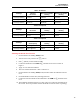
Resistance Measurement Test
1. Put the calibrator in Standby (
STBY) mode.
2. Put the UUT rotary switch in the
V position.
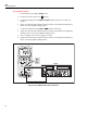
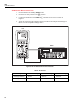
3. Connect the
OUTPUT and SENSE leads of the calibrator to the UUT as shown by the
solid and dotted lines in Figure 7.
4. Apply the calibrator resistance values in Table 8 in the 789 400 Ω to 40 kΩ range.
Compare the readings on the UUT to the acceptable readings shown.
5. Change the connections to the UUT. Using the Fluke 5440A-7002 low thermal leads,
connect the calibrator to the UUT as shown by the solid lines in Figure 7.
6. Apply the rest of the calibrator resistance values in Table 8 (400 kΩ range and
above). Compare the readings on the UUT to the acceptable readings shown.
UUT
5500A
adm004F.EPS
Figure 7. Resistance Measurement Test Connections