® 80 Series III Multimeters Users Manual October 1997 Rev.5, 12/03 1997-2003 Fluke Corporation, All rights reserved. All product names are trademarks of their respective companies.
Lifetime Limited Warranty Each Fluke 20, 70, 80, 170 and 180 Series DMM will be free from defects in material and workmanship for its lifetime. As used herein, “lifetime” is defined as seven years after Fluke discontinues manufacturing the product, but the warranty period shall be at least ten years from the date of purchase.
Table of Contents Title Introduction.................................................................................................................... Safety Information ......................................................................................................... Your Meter’s Features ................................................................................................... Power-Up Options ..............................................................................................
80 Series III Users Manual Analog Bar Graph .......................................................................................................... Model 87 Bar Graph.................................................................................................. Models 83 and 85 Bar Graph .................................................................................... 4-1/2 Digit Mode (Model 87) ..........................................................................................
List of Tables Table 1. 2. 3. 4. 5. 6. 7. 8. 9. 10. 11. 12. 13. 14. 15. 16. 17. 18. 19. Title Page International Electrical Symbols ......................................................................................... Inputs ................................................................................................................................. Rotary Switch Positions ..................................................................................................... Pushbuttons ............
80 Series III Users Manual iv
List of Figures Figure Title Page 1. 2. 3. 4. 5. 6. 7. 8. 9. 10. 11. Display Features (Model 87 Shown).......................................................... Measuring AC and DC Voltage.................................................................. Testing for Continuity................................................................................. Measuring Resistance ............................................................................... Measuring Capacitance..........................
0 Series III Users Manual vi
Introduction Introduction WWarning Read "Safety Information" before you use the meter. Except where noted, the descriptions and instructions in this manual apply to Series III Models 83, 85, 87, and 87/E multimeters. Model 87 is shown in all illustrations. In this manual, a Warning identifies conditions and actions that pose hazards to the user. A Caution identifies conditions and actions that may damage the meter or the equipment under test.
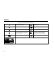
80 Series III Users Manual Table 1. International Electrical Symbols AC (Alternating Current) Earth ground DC (Direct Current) Fuse AC or DC Conforms to European Union directives Refer to the manual for information about this feature. Conforms to relevant Canadian Standards Association directives Battery Double insulated Inspected and licensed by TÜV Product Services.
Safety Information • Remove test leads from the meter before you open the battery door. • Inspect the test leads for damaged insulation or exposed metal. Check the test leads for continuity. Replace damaged test leads before you use the meter. Caution To avoid possible damage to the meter or to the equipment under test, follow these guidelines: • Do not use the meter if it operates abnormally. Protection may be impaired. When in doubt, have the meter serviced.
80 Series III Users Manual To protect yourself, use the following guidelines: • Use caution when working with voltages above 30 V ac rms, 42 V ac peak, or 60 V dc. Such voltages pose a shock hazard. Table 2. Inputs Terminal Description Page A 22 When using the probes, keep your fingers behind the finger guards. Input for 0 A to 10.00 A current measurements mA µA 22 Connect the common test lead before you connect the live test lead.
Your Meter’s Features Table 3. Rotary Switch Positions Switch Position Function Page K AC voltage measurement 12 L DC voltage measurement 12 d mV 400 mV dc voltage range 12 R Continuity test 14 e Resistance measurement 16 E Capacitance measurement 18 Diode test 21 mA A DC or AC current measurements from 0 mA to 10.
80 Series III Users Manual Table 4. Pushbuttons Button Function U ReE (Blue button) Page Selects capacitance. 18 mA/A, µA Switches between dc and ac current. 22 Power-up Disables automatic power-off feature. 11 Starts recording of minimum and maximum values. Steps the display through MIN, MAX, AVG (average), and present readings. 30 position Power-up Enables high-accuracy 1-second response time for MIN MAX recording.
Your Meter’s Features Table 4. Pushbuttons (cont) Button b Model 87: yellow button Function Page Any switch position Turns the backlight on and off. NA For Model 87, hold the yellow button down for one second to enter the 4-1/2 digit mode. To return to the 3-1/2 digit mode, hold the button down only until all display segments turn on (about one second). 29 Continuity ReE Turns the continuity beeper on and off.
80 Series III Users Manual 6 8 7 9 5 4 10 10 3 2 1011 1 12 13 iy1f.eps Figure 1.
Your Meter’s Features Table 5. Display Features Number Feature A ± B C D Page Polarity indicator for the analog bar graph. 28 Q Relative (REL) mode is active. 32 S The continuity beeper is on. 14 Indicates negative readings. In relative mode, this sign indicates that the present input is less than the stored reference. 32 - E The battery is low.
80 Series III Users Manual Table 5. Display Features (continued) Number Feature J A, µA, mA V, mV µF, nF nS % e, Me, ke Hz, kHz, MHz 10 Indication Page A: Amperes (amps). The unit of current. µA: Microamp. 1 x 10⁻⁶ or 0.000001 amperes. mA: Milliamp. 1 x 10⁻³ or 0.001 amperes. 22 V: Volts. The unit of voltage. mV: Millivolt. 1 x 10⁻³ or 0.001 volts. 12 F: Farad. The unit of capacitance. µF: Microfarad. 1 x 10⁻⁶ or 0.000001 farads. nF: Nanofarad. 1 x 10⁻⁹ or 0.000000001 farads. 18 S: Siemen.
Your Meter’s Features Table 5. Display Features (continued) Number Feature K 4000 mV L Analog bar graph M 0L Indication Displays the currently selected range. Provides an analog indication of the present inputs. The input (or the relative value when in relative mode) is too large for the selected range. For duty cycle measurements OL is displayed when the input signal stays high or low. Page See specifications for ranges for each function.
80 Series III Users Manual Input Alert™ Feature Measuring AC and DC Voltage If a test lead is plugged into the mA/µA or A terminal, but the rotary switch is not correctly set to the mA/µA or A position, the beeper warns you by making a chirping sound. This warning is intended to stop you from attempting to measure voltage, continuity, resistance, capacitance, or diode values when the leads are plugged into a current terminal.
Making Measurements The following are some tips for measuring voltage: • • AC Voltage When you measure voltage, the meter acts approximately like a 10 MΩ (10,000,000 Ω) impedance in parallel with the circuit. This loading effect can cause measurement errors in highimpedance circuits. In most cases, the error is negligible (0.1% or less) if the circuit impedance is 10 kΩ (10,000 Ω) or less.
80 Series III Users Manual Testing for Continuity Caution To avoid possible damage to the meter or to the equipment under test, disconnect circuit power and discharge all high-voltage capacitors before testing for continuity. Continuity is the presence of a complete path for current flow. The continuity test features a beeper that sounds if a circuit is complete. The beeper allows you to perform quick continuity tests without having to watch the display.
Making Measurements For in-circuit tests, turn circuit power off. 87 III TRUE RMS MULTIMETER MIN MAX RANGE HOLD REL 4 1/2 DIGITS 1 Seconds Activates continuity beeper 87 III TRUE RMS MULTIMETER MIN MAX H RANGE 4 1/2 DIGITS 1 Seconds H Hz PEAK MIN MAX mV mV mA A V mA A V µA V µA V OFF OFF A mA µA COM V ! ! 10A MAX FUSED HOLD REL Hz PEAK MIN MAX 400mA MAX FUSED CAT II 10A MAX FUSED 1000V MAX ! 400mA MAX FUSED CAT II 1000V MAX ! ON (closed) OFF (open) iy4f.
80 Series III Users Manual Measuring Resistance Caution To avoid possible damage to the meter or to the equipment under test, disconnect circuit power and discharge all high-voltage capacitors before measuring resistance. Resistance is an opposition to current flow. The unit of resistance is the ohm (Ω). The meter measures resistance by sending a small current through the circuit.
Making Measurements In-Circuit Resistance Measurements Isolating a Potentiometer Circuit Power OFF 1 3 2 Disconnect 2 1 87 III TRUE RMS MULTIMETER 3 MIN MAX RANGE HOLD REL 4 1/2 DIGITS 1 Seconds Isolating a Resistor H Hz PEAK MIN MAX mV mA A V µA V OFF A mA µA V COM ! 10A MAX FUSED 400mA MAX FUSED CAT II 1000V MAX ! Disconnect iy6f.eps Figure 4.
80 Series III Users Manual Using Conductance for High Resistance or Leakage Tests The following are some tips for measuring conductance: • High-resistance readings are susceptible to electrical noise. To smooth out most noisy readings, enter the MIN MAX recording mode; then scroll to the average (AVG) reading. • There is normally a residual conductance reading with the test leads open. To ensure accurate readings, use the relative (REL) mode to subtract the residual value.
Making Measurements The meter measures capacitance by charging the capacitor with a known current for a known period of time, measuring the resulting voltage, then calculating the capacitance. The measurement takes about 1 second per range. The capacitor charge can be up to 1.2 V. 87 III TRUE RMS MULTIMETER µ nF MIN MAX RANGE HOLD REL Select Capacitance H Hz 4 1/2 DIGITS PEAK MIN MAX 1 Seconds The meter’s capacitance ranges are 5 nF, 0.05 µF, 0.5 µF, and 5 µF.
80 Series III Users Manual • To estimate capacitance values above 5 µF, use the current supplied by the meter’s resistance function, as follows: 1. Set up the meter to measure resistance. 2. Press Kto select a range based on the value of capacitance you expect to measure (refer to Table 6.) 3. Discharge the capacitor. 4. Place the meter’s leads across the capacitor; then time how long it takes for the display to reach OL. 5.
Making Measurements Testing Diodes Forward Bias Caution To avoid possible damage to the meter or to the equipment under test, disconnect circuit power and discharge all high-voltage capacitors before testing diodes. 87 III TRUE RMS MULTIMETER MIN MAX RANGE HOLD REL 4 1/2 DIGITS Typical Reading + H Hz PEAK MIN MAX 1 Seconds mV mA A V µA V OFF Use the diode test to check diodes, transistors, silicon controlled rectifiers (SCRs), and other semiconductor devices.
80 Series III Users Manual Measuring AC or DC Current WWarning Never attempt an in-circuit current measurement where the open-circuit potential to earth is greater than 1000 V. You may damage the meter or be injured if the fuse blows during such a measurement. Caution To avoid possible damage to the meter or to the equipment under test, check the meter’s fuses before measuring current. Use the proper terminals, function, and range for your measurement.
Making Measurements 1 Circuit Power: OFF to connect meter. ON for measurement. OFF to disconnect meter. Total current to circuit 4 87 III TRUE RMS MULTIMETER 5 AC DC MIN MAX RANGE HOLD REL 4 1/2 DIGITS 1 Seconds Hz PEAK MIN MAX mV mA A µA Current through one component mA A V µA V 2 OFF A 3 H mA µA COM V ! 10A MAX FUSED 400mA MAX FUSED CAT II 1000V MAX ! 5 iy7f.eps Figure 7.
80 Series III Users Manual 3. If you are using the A terminal, set the rotary switch to mA/A. If you are using the mA/µA terminal, set the rotary switch to µA for currents below 4000 µA (4 mA), or mA/A for currents above 4000 µA. 4. To measure ac current, press the blue button. 5. Break the circuit path to be tested. Touch the black probe to the more negative side of the break; touch the red probe to the more positive side of the break.
Making Measurements Measuring Frequency The following are some tips for measuring frequency: Frequency is the number of cycles a signal completes each second. The meter measures the frequency of a voltage or current signal by counting the number of times the signal crosses a threshold level each second. • If a reading shows as 0 Hz or is unstable, the input signal may be below or near the trigger level.
80 Series III Users Manual Table 7. Functions and Trigger Levels for Frequency Measurements Function K Approximate Trigger Level Typical Application 4 V, 40 V, 400 V, 1000 V 0V Most signals. 400 mV 0V High-frequency 5 V logic signals. (The dc-coupling of the L function can attenuate high-frequency logic signals, reducing their amplitude enough to interfere with triggering.) L 400 mV 40 mV Refer to the measurement tips given before this table. L 4V 1.7 V 5 V logic signals (TTL).
Making Measurements frequency function, you can change the slope for the meter’s counter by pressing T. Measuring Duty Cycle Duty cycle (or duty factor) is the percentage of time a signal is above or below a trigger level during one cycle (Figure 8). The duty cycle mode is optimized for measuring the on or off time of logic and switching signals.
80 Series III Users Manual Determining Pulse Width Analog Bar Graph For a periodic waveform (its pattern repeats at equal time intervals), you can determine the amount of time that the signal is high or low as follows: The analog bar graph functions like the needle on an analog meter, but without the overshoot. The bar graph is updated 40 times per second.
4-1/2 Digit Mode (Model 87) Models 83 and 85 Bar Graph 4-1/2 Digit Mode (Model 87) The bar graph on Models 83 and 85 consists of 43 segments. The number of lit segments is relative to the full-scale value of the selected range. The polarity indicator at the left of the graph indicates the polarity of the input. For example, if the 40 V range is selected, the "4" on the scale represents 40 V. An input of -30 V would light the negative sign and the segments up to the "3" on the scale.
80 Series III Users Manual MIN MAX Recording Mode The MIN MAX mode records minimum and maximum input values. When the inputs go below the recorded minimum value or above the recorded maximum value, the meter beeps and records the new value. This mode can be used to capture intermittent readings, record maximum readings while you are away, or record readings while you are operating the equipment under test and cannot watch the meter.
MIN MAX Recording Mode Table 8. MIN MAX Functions Button MIN MAX Function M Enter MIN MAX recording mode. The meter is locked in the range displayed before you entered MIN MAX mode. (Select the desired measurement function and range before entering MIN MAX.) The meter beeps each time a new minimum or maximum value is recorded. M Scroll through minimum (MIN), maximum (MAX), and average (AVG) values. (While in MIN MAX mode) T PEAK MIN MAX Model 87 only: Select 100 ms or 250 µs response time.
80 Series III Users Manual Touch Hold ® Mode WWarning The Touch Hold mode will not capture unstable or noisy readings. Do not use Touch Hold mode to determine that circuits are without power. The Touch Hold mode captures the present reading on the display. When a new, stable reading is detected, the meter beeps and displays the new reading. To enter or exit Touch Hold mode, press I.
Maintenance Uses for the Zoom Mode (Models 83 and 85) Maintenance The relative mode, combined with the increased sensitivity of the bar graph’s zoom mode, helps you make fast and accurate zero and peak adjustments. Repairs or servicing not covered in this manual should be performed only by qualified personnel as described in the 80 Series III Service Manual.
80 Series III Users Manual Testing the Fuses Before measuring current, test the appropriate fuse as shown in Figure 9. If the tests give readings other than those shown, have the meter serviced. Good F2 fuse: 00.0 Ω to 00.5 Ω Replace fuse: OL 87 TRUE RMS MULTIMETER MIN MAX RANGE HOLD REL mA A V µA V WWarning To avoid electrical shock or personal injury, remove the test leads and any input signals before replacing the battery or fuses.
Maintenance Replacing the Battery Replacing the Fuses Replace the battery with a 9 V battery (NEDA A1604, 6F22, or 006P). Referring to Figure 10, examine or replace the meter’s fuses as follows: WWarning To avoid false readings, which could lead to possible electric shock or personal injury, replace the battery as soon as the battery indicator (B) appears. Replace the battery as follows (refer to Figure 10): 1. 2. 3. Turn the rotary switch to OFF and remove the test leads from the terminals.
80 Series III Users Manual 6. Verify that the rotary switch and the circuit board switch are in the OFF position. 7. Replace the case top, ensuring that the gasket is properly seated and case snaps together above the LCD (item A). 8. Reinstall the three screws and the battery door. Secure the door by turning the screws one-quarter turn clockwise. Service and Parts If the meter fails, check the battery and fuses. Review this manual to verify proper use of the meter.
Service and Parts F1 F2 1 iy12f.eps Figure 10.
80 Series III Users Manual Table 9. Replacement Parts Item Description BT1 Battery, 9 V F1 W Fuse, 0.440 A, 1000 V, FAST F2 W Fuse, 11 A, 1000 V, FAST H1 Screw, Case MP1 Foot, Non-Skid MP2 O-Ring, Input Receptacle TM1 CD-ROM (contains Users Manual) TM2 Getting Started Manual TM3 Quick Reference Guide, Fluke 80 Series III TM4 Service Manual WTo ensure safety, use exact replacement only.
Service and Parts TL75 Test Lead Set MP85 T24 Test Lead Set S1 TP1, TP4 Probes AC20 Alligator Clip (Black) 87/E Test Lead Set F2 AC70A Alligator Clips F1 MP2 TM1 C81Y MP86 TM2 H1 BT1 MP1 MP92 TM3 H5, 6 iy11f.eps Figure 11.
80 Series III Users Manual Table 10.
Specifications Specifications Maximum Voltage between any Terminal and Earth Ground: 1000 V rms WFuse Protection for mA or µA inputs: 44/100 A, 1000 V FAST Fuse WFuse Protection for A input: 11 A, 1000 V FAST Fuse Display: Digital: 4000 counts updates 4/sec; (Model 87 also has 19,999 counts in 4½-digit mode, updates 1/sec.). Analog: updates 40/sec. Frequency: 19,999 counts, updates 3/sec at >10 Hz. Model 87: 4 x 32 segments (equivalent to 128); Models 83, 85: 43 segments.
80 Series III Users Manual Table 11. Models 85 and 87 AC Voltage Function Specifications Function K3 Range 400.0 mV 4.000 V 40.00 V 400.0 V 1000 V Accuracy1 Resolution 0.1 mV 0.001 V 0.01 V 0.1 V 1V 50 Hz - 60 Hz ±(0.7% + 4) ±(0.7% + 2) ±(0.7% + 2) ±(0.7% + 2) ±(0.7% + 2) 45 Hz - 1 kHz ±(1.0% + 4) ±(1.0% + 4) ±(1.0% + 4) ±(1.0% + 4) ±(1.0% + 4)5 1 kHz - 5 kHz ±(2.0% + 4) ±(2.0% + 4) ±(2.0% + 4) ±(2.0% + 4)4 unspecified 5 kHz - 20 kHz2 ±(2.0% + 20) ±(2.0% + 20) ±(2.
Specifications Table 12. Model 83 AC Voltage Function Specifications Function K 2 Range 400.0 mV 4.000 V 40.00 V 400.0 V 1000 V Accuracy1 Resolution 0.1 mV 0.001 V 0.01 V 0.1 V 1V 50 Hz - 60 Hz ±(0.5% + 4) ±(0.5% + 2) ±(0.5% + 2) ±(0.5% + 2) ±(0.5% + 2) 1. 2. See the first sentence in Table 11 for a complete explanation of accuracy. Below a reading of 200 counts, add 10 counts. 3. Frequency range: 1 kHz to 2.5 kHz. 45 Hz - 1 kHz ±(1.0% + 4) ±(1.0% + 4) ±(1.0% + 4) ±(1.0% + 4) ±(1.
80 Series III Users Manual Table 13. DC Voltage, Resistance, and Conductance Function Specifications Accuracy1 Function L F Range Resolution Model 83 Model 85 Model 87 4.000 V 40.00 V 400.0 V 1000 V 0.001 V 0.01 V 0.1 V 1V ±(0.1% + 1) ±(0.1% + 1) ±(0.1% + 1) ±(0.1% + 1) ±(0.08% + 1) ±(0.08% + 1) ±(0.08% + 1) ±(0.08% + 1) ±(0.05% + 1) ±(0.05% + 1) ±(0.05% + 1) ±(0.05% + 1) 400.0 mV 0.1 mV ±(0.3% + 1) ±(0.1% + 1) ±(0.1% + 1) 400.0 Ω 4.000 kΩ 40.00 kΩ 400.0 kΩ 4.000 MΩ 40.00 MΩ 40.00 nS 0.
Specifications Table 14. Current Function Specifications Accuracy1 Function mA \ (45 Hz to 2 kHz) Range 40.00 mA 400.0 mA 4000 mA 10.00 A5 Resolution 0.01 mA 0.1 mA 1 mA 0.01 A Model 832 Model 853, 4 Model 873, 4 Burden Voltage (typical) ±(1.2% + 2)6 ±(1.2% + 2)6 ±(1.2% + 2)6 ±(1.2% + 2)6 ±(1.0% + 2)6 ±(1.0% + 2)6 ±(1.0% + 2)6 ±(1.0% + 2)6 ±(1.0% + 2) ±(1.0% + 2) ±(1.0% + 2) ±(1.0% + 2) 1.8 mV/mA 1.8 mV/mA 0.03 V/A 0.03 V/A ±(0.2% + 4) ±(0.2% + 2) ±(0.2% + 4) ±(0.2% + 2) ±(0.2% + 4) ±(0.
80 Series III Users Manual Table 14. Current Function Specifications (continued) Accuracy1 Function µA B (45 Hz to 2 kHz) Range Resolution Model 832 Model 853, 4 Model 873, 4 Burden Voltage (typical) 400.0 µA 4000 µA 0.1 µA 1 µA ±(1.2% + 2)5 ±(1.2% + 2)5 ±(1.0% + 2)5 ±(1.0% + 2)5 ±(1.0% + 2) ±(1.0% + 2) 100 µV/µA 100 µV/µA 400.0 µA 4000 µA 0.1 µA 1 µA ±(0.4% + 4) ±(0.4% + 2) ±(0.2% + 4) ±(0.2% + 2) ±(0.2% + 4) ±(0.2% + 2) 100 µV/µA 100 µV/µA µAF 1.
Specifications Table 15. Capacitance and Diode Function Specifications Function E G 1. Range Accuracy1 Resolution 5.00 nF 0.0500 µF 0.500 µF 5.00 µF 0.01 nF 0.0001 µF 0.001 µF 0.01 µF ±(1% + 3) ±(1% + 3) ±(1% + 3) ±(1.9% + 3) 3.000 V 0.001 V ±(2% + 1) With a film capacitor or better, using Relative mode to zero residual. See the first sentence in Table 11 for a complete explanation of accuracy. Table 16. Frequency Counter Specifications Function Frequency (0.
80 Series III Users Manual Table 17. Frequency Counter Sensitivity and Trigger Levels Minimum Sensitivity (RMS Sinewave) Input Range1 400 mV dc 400 mV dc 4V 40 V 400 V 1000 V 5 Hz - 20 kHz 70 mV (to 400 Hz) 150 mV 0.3 V 3V 30 V 300 V 0.5 Hz - 200 kHz (DC Voltage Function) 40 mV 1.7 V 4V 40 V 400 V 70 mV (to 400 Hz) 150 mV 0.7 V 7 V (≤140 kHz) 70 V (≤14.0 kHz) 700 V (≤1.4 kHz) Duty Cycle Range 0.0 to 99.9% Approximate Trigger Level Accuracy Within ±(0.05% per kHz + 0.
Specifications Table 18. Electrical Characteristics of the Terminals Overload Protection1 Input Impedance (nominal) Common Mode Rejection Ratio (1 kΩ unbalance) Normal Mode Rejection L 1000 V rms 10 MΩ<100 pF >120 dB at dc, 50 Hz or 60 Hz >60 dB at 50 Hz or 60 Hz F mV 1000 V rms 10 MΩ<100 pF >120 dB at dc, 50 Hz or 60 Hz >60 dB at 50 Hz or 60 Hz K 1000 V rms 10 MΩ<100 pF (ac-coupled) >60 dB, dc to 60 Hz Open Circuit Full Scale Voltage Function Test Voltage e 1000 V rms <1.
80 Series III Users Manual Table 19.