
Application Note


8 Fluke Corporation Troubleshooting power harmonics
The presence of harmonics
was obvious by comparison of
phase current and neutral cur-
rent measurements. As Table 1
shows, the neutral current was
substantially higher than any of
the phase currents, even though
the phase currents were relatively
well balanced. The average-
responding meter consistently
took readings approximately 20
percent low on all the phases.
Its neutral current readings were
only 2 percent low.
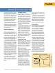
The waveforms explain the
discrepancy. The phase currents
were badly distorted by large
amounts of third harmonic cur-
rent, while the neutral current
was nearly a pure sinewave at
the third harmonic frequency.
The phase current readings
listed in Table 1 demonstrate
clearly why true-rms measure-
ment capability is required to
accurately determine the value of
harmonic currents.
The next step was to calculate
the “harmonic derating factor” or
HDF (Refer to “Derating trans-
formers” section on page 6.)
The results indicated that,
with the level of harmonics
present, the transformer should
be derated to 72.3 percent of
its nameplate rating to prevent
overheating. In this case the
transformer should be derated
to 72.3 percent of its 225 kVA
rating, or derated to 162.7 kVA.
The actual load was calcu-
lated to be 151.3 kVA. Although
that figure was far less than the
nameplate rating, the transformer
was operating close to its derated
capacity.
Subpanel—Next a subpanel
which supplied branch circuits
for the 120 V receptacles was
examined. The current in each
neutral was measured and
recorded (see Table 2).
When a marginal or over-
loaded conductor was identified,
the associated phase currents
and the neutral-to-ground
voltage at the receptacle were
also measured. When a check
of neutral #6 revealed 15 A in
a conductor rated for 16 A, the
phase currents of the circuits
Figure 4. Phase current.
Figure 5. Neutral current.
Circuit
number
Phase
current
(amps)
Neutral-to-ground voltage
drop at receptacle
25 7.8 3.75 V
27 9.7 4.00 V
29 13.5 8.05 V
Table 3. Phase currents and neutral-to-ground voltage for neutral #06.
Neutral
conductor
number
Current
(amps)
01 5.0
02 11.3
03 5.0
04 13.1
05 12.4
06 15.0*
07 1.8
08 11.7
09 4.5
10 11.8
11 9.6
12 11. 5
13 11.3
14 6.7
15 7.0
16 2.3
17 2.6
Table 2. Subpanel branch circuit neutral
currents.
(#25, #27, and #29) that shared
that neutral were also measured
(Table 3). Note that each of the
phase currents of these three
branch circuits was substan-
tially less than 15 A, and also
the same phase conductors had
significant neutral-to-ground
voltage drops.
In the branch circuits which
had high neutral current, the
relationship between the neutral
and the phase currents was
similar to that of the transformer
secondary. The neutral cur-
rent was higher than any of the
associated phase currents. The
danger here is that the neutral
conductors could become over-
loaded and not offer the warning
signs of tripped circuit breakers.
Recommendations
1. Refrain from adding addi-
tional loads to the receptacle
transformer unless steps are
taken to reduce the level of
harmonics.
2. Pull in extra neutrals to the
branch circuits that are heav-
ily loaded.
3. Monitor the load currents on a
regular basis using true-rms
measuring test equipment.
Fluke Corporation
PO Box 9090, Everett, WA 98206 U.S.A.
Fluke Europe B.V.
PO Box 1186, 5602 BD
Eindhoven, The Netherlands
For more information call:
In the U.S.A. (800) 443-5853 or
Fax (425) 446-5116
In Europe/M-East/Africa +31 (0) 40 2675 200 or
Fax +31 (0) 40 2675 222
In Canada (800)-36-FLUKE or
Fax (905) 890-6866
From other countries +1 (425) 446-5500 or
Fax +1 (425) 446-5116
Web access: http://www.fluke.com
©2003-2009 Fluke Corporation.
Specifications subject to change without notice.
Printed in U.S.A. 6/2009 1260362K A-EN-N
Modification of this document is not permitted
without written permission from Fluke Corporation.
Fluke. Keeping your world
up and running.
®