
User's Manual

Digital Multimeter
Performance Tests
15
Basic Operability Tests
Refer to the following sections to test the basic operability of the Meter.
Testing the Fuses
Refer to “Testing the Fuses”.
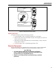
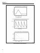
Testing the Display
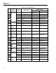
Turn the Meter on while holding down D to view all segments of the display.
Compare the display with the appropriate examples in Figure 4 and Table 14.
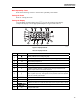
ayi04.eps
Figure 4. Display Features
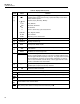
Table 14. Display Features
Number Feature Indication
Y
Polarity indicator for the analog bar graph.
A
TrigY
Positive or negative slope indicator for Hz/duty cycle triggering.
B X
The continuity beeper is on.
C W
Relative (REL) mode is active.
D g
Smoothing is active.
E
-
Indicates negative readings. In relative mode, this sign indicates that the
present input is less than the stored reference.
F
Z
Indicates the presence of a high voltage input. Appears if the input voltage is
30 V or greater (ac or dc). Also appears in low pass filter mode. Also appears
in cal, Hz, and duty cycle modes.
G
RS
AutoHOLD is active.
H
S
Display Hold is active.
I
p
Indicates the Meter is in Peak Min Max mode and the response time is 250 µs
J
m MAX
MIN AVG
Indicators for minimum-maximum recording mode.
K
K
Low pass filter mode.