Hart Scientific 9150 Portable Furnace User’s Guide Rev.
Fluke Corporation, Hart Scientific Division 799 E. Utah Valley Drive • American Fork, UT 84003-9775 • USA Phone: +1.801.763.1600 • Telefax: +1.801.763.1010 E-mail: support@hartscientific.com www.hartscientific.com Subject to change without notice. • Copyright © 2005 • Printed in USA Rev.
Table of Contents 1 Before You Start . . . . . . . . . . . . . . . . . . . . . . . . . . 1 1.1 1.2 Symbols Used . . . . . . . . . . . . . . . . . . . . . . . . . . . . 1 Safety Information . . . . . . . . . . . . . . . . . . . . . . . . . . 2 1.2.1 1.2.2 1.3 WARNINGS . . . . . . . . . . . . . . . . . . . . . . . . . . . . . . . . . . . 2 CAUTIONS . . . . . . . . . . . . . . . . . . . . . . . . . . . . . . . . . . . 3 Authorized Service Centers. . . . . . . . . . . . . . . . . . . . . .
8.2.1 8.2.2 8.2.3 8.3 Programmable Set-points . . . . . . . . . . . . . . . . . . . . . . . . . . . . 21 Set-point Value . . . . . . . . . . . . . . . . . . . . . . . . . . . . . . . . . 23 Temperature Scale Units . . . . . . . . . . . . . . . . . . . . . . . . . . . . 23 Scan . . . . . . . . . . . . . . . . . . . . . . . . . . . . . . . . . 24 8.3.1 8.3.2 8.4 Scan Control . . . . . . . . . . . . . . . . . . . . . . . . . . . . . . . . . . 24 Scan Rate . . . . . . . . . . . . . . . . . . . . . . . . .
10.2.1 Stabilization and Accuracy . . . . . . . . . . . . . . . . . . . . . . . . . . . 43 11 Calibration Procedure . . . . . . . . . . . . . . . . . . . . . . 45 11.1 Calibration Points . . . . . . . . . . . . . . . . . . . . . . . . . . 45 11.2 Calibration Procedure . . . . . . . . . . . . . . . . . . . . . . . . 45 12 Maintenance . . . . . . . . . . . . . . . . . . . . . . . . . . . 47 13 Troubleshooting. . . . . . . . . . . . . . . . . . . . . . . . . . 49 13.1 13.
1 Before You Start Symbols Used 1 1.1 Before You Start Symbols Used Table 1 lists the International Electrical Symbols. Some or all of these symbols may be used on the instrument or in this manual.
9150 Portable Furnace User’s Guide Symbol Description Canadian Standards Association OVERVOLTAGE (Installation) CATEGORY II, Pollution Degree 2 per IEC1010-1 refers to the level of Impulse Withstand Voltage protection provided. Equipment of OVERVOLTAGE CATEGORY II is energy-consuming equipment to be supplied from the fixed installation. Examples include household, office, and laboratory appliances.
1 Before You Start Safety Information DO NOT operate this unit without a properly grounded, properly polarized power cord. DO NOT connect this unit to a non-grounded, non-polarized outlet. HIGH VOLTAGE is used in the operation of this equipment. SEVERE INJURY OR DEATH may result if personnel fail to observe safety precautions. Before working inside the equipment, turn the power off and disconnect the power cord. Always replace the fuse with one of the same rating, voltage, and type.
150 Portable Furnace User’s Guide Allow for test probe expansion inside the well as the furnace heats. DO NOT use fluids to clean out the well. Never introduce foreign material into the probe hole of the insert. Fluids, etc. can leak into the calibrator causing damage. DO NOT change the values of the calibration constants from the factory set values. The correct setting of these parameters is important to the safety and proper operation of the calibrator.
1 Before You Start Authorized Service Centers Chao Yang District Beijing 100004, PRC CHINA Phone: +86-10-6-512-3436 Telefax: +86-10-6-512-3437 E-mail: xingye.han@fluke.com.cn Fluke South East Asia Pte Ltd. Fluke ASEAN Regional Office Service Center 60 Alexandra Terrace #03-16 The Comtech (Lobby D) 118502 SINGAPORE Phone: +65 6799-5588 Telefax: +65 6799-5588 E-mail: antng@singa.fluke.
2 Introduction 2 Introduction The Hart Scientific 9150 thermocouple furnace can be used for calibrating thermocouple and RTD temperature probes. Calibrations may be done over a range of 150°C to 1200°C (302°F to 2192°F). Temperature display of the 9150 is 0.1 degrees below 1000°and 1 degrees above 1000°.
3 Specifications and Environmental Conditions Specifications 3 3.1 3.2 Specifications and Environmental Conditions Specifications Temperature Range 150–1200°C (302–2192°F) Display Resolution 0.1° to 999.9°, 1° above 1000° Stability ±0.5°C Display Accuracy ±5.0°C Well Diameter 1.25" (32 mm) Well Depth 4" (102 mm) Heating Time 35 minutes to 1200°C Cooling Time 140 minutes with block Well to Well Uniformity ±0.5°C to ±1.
9150 Portable Furnace User’s Guide 3.3 Warranty Fluke Corporation, Hart Scientific Division (Hart) warrants this product to be free from defects in material and workmanship under normal use and service for a period as stated in our current product catalog from the date of shipment. This warranty extends only to the original purchaser and shall not apply to any product which, in Hart's sole opinion, has been subject to misuse, alteration, abuse or abnormal conditions of operation or handling.
4 Safety Guidelines 4 Safety Guidelines • Operate the instrument in room temperatures between 5-50°C (41-122°F). Allow sufficient air circulation by leaving at least 6 inches of space between the instrument and nearby objects. Overhead clearance needs to allow for safe and easy insertion and removal of probes for calibration. • The furnace is a precision instrument. Although it has been designed for optimum durability and trouble free operation, it must be handled with care.
5 Quick Start Unpacking 5 5.1 Quick Start Unpacking Unpack the furnace carefully and inspect it for any damage that may have occurred during shipment. If there is shipping damage, notify the carrier immediately. Verify that the following components are present: • 9150 Furnace • 3150, Insert • Insert Insulator • Power Cord • Manual • RS-232 Cable 5.2 Set-Up Place the calibrator on a flat surface with at least 6 inches of free space around the instrument. Plug the power cord into a grounded mains outlet.
9150 Portable Furnace User’s Guide 5.4 Setting the Temperature Section 8 explains in detail how to set the temperature set-point on the calibrator using the front panel keys. The procedure is summarized here. (1) Press “SET” twice to access the set-point value. (2) Press “SET” to move the cursor to the units that need changing. (3) Press “UP” or “DOWN” to change the set-point value. (4) Press “SET” until the display exits to store the new set-point.
6 Parts and Controls Back Panel 6 Parts and Controls The user should become familiar with the furnace back panel, front panel, and constant temperature block assembly. 6.1 Back Panel The back panel (Figure 1) features the Power Entry Module (PEM) that contains the power cord socket, the power switch, and the heater voltage switch, the serial port, and the fan. Figure 1 Back Panel Power Cord - On the back of the calibrator is the removable power cord inlet that plugs into an IEC grounded socket.
9150 Portable Furnace User’s Guide Fan - The fan inside the calibrator runs continuously when the unit is being operated to provide cooling for the instrument. Slots at the top and sides of the calibrator are provided for airflow. The area around the calibrator must be kept clear to allow adequate ventilation. The airflow is directed upward and can be extremely hot. 6.2 Front Panel The front panel consists of the controller display and the controller keypad as shown in Figure 2.
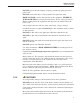
6 Parts and Controls Constant Temperature Block Assembly EXIT – Used to exit from a menu. When EXIT is pressed any changes made to the displayed value are ignored. 6.3 Constant Temperature Block Assembly The constant temperature block assembly is shown in Figure 3 and consists of removable inserts. Figure 3 Removable Inserts 6.3.
9150 Portable Furnace User’s Guide • Insert A Model 3150-2 (variety block): 1/2”, 1/4”, 3/8”, 3/16”, 1/8”, and 1/16” holes • Insert B Model 3150-3 (comparison block): two each 3/8”, 1/4”, and 3/16” holes or • Insert C Model 3150-4 (1/4” comparison block): six 1/4” holes 18
7 General Operation Changing Display Units 7 7.1 General Operation Changing Display Units The 9150 can display temperature in Celsius or Fahrenheit. The temperature units are shipped from the factory set to Celsius. To change to Fahrenheit or back to Celsius there are two ways: 1 - Press the “SET” and “DOWN” simultaneously. or 1 - Press the “SET” key three times from the temperature display and then “EXIT” to show the units. Un= C 2 - Press the “UP” or “DOWN” key to change units.
8 Controller Operation Well Temperature 8 Controller Operation This section discusses in detail how to operate the furnace temperature controller using the front control panel.
9150 Portable Furnace User’s Guide Figure 4 Controller Operation Flowchart 22
8 Controller Operation Temperature Set-point 200.0 C S Well temperature in degrees Celsius Access set-point memory 1. 200. Set-point memory 1, 200.0°C currently used To change the set-point memory press “UP” or “DOWN”. 5. 900. New set-point memory 5, 900.0°C Press “SET” to accept the new selection and access the set-point value. S 8.2.2 Accept selected set-point memory Set-point Value The set-point value may be adjusted after selecting the set-point memory and pressing “SET”. 0900.
9150 Portable Furnace User’s Guide Scale units currently selected Press “UP” or “DOWN” to change the units. Un= F New units selected Press “EXIT” to display the well temperature or press “SET” to access the scan control. 8.3 Scan The scan rate can be set and enabled so that when the set-point is changed the furnace heats or cools at a specified rate (degrees per minute) until it reaches the new set-point. With the scan disabled the furnace heats or cools at the maximum possible rate. 8.3.
8 Controller Operation Ramp and Soak Program Press “SET” to accept the new scan rate and continue. S 8.4 Accept scan rate Ramp and Soak Program The ramp and soak program feature for the 9150 allows the user to program a number of set-points, cycle the furnace automatically between the temperatures at a scan rate set by the user, and hold the furnace at each temperature for a period of time set by the user. The user can select one of four different cycle functions.
9150 Portable Furnace User’s Guide 8.4.3 Program Set-Points The controller allows the user to adjust up to eight program points. These are accessed by pressing “SET” after setting the number of program points as described in Section 8.4.2. Each program point has three associated parameters: the program set-point, the program scan rate, and the program hold (or soak) time. After adjusting the number of program points press “SET”.
8 Controller Operation Ramp and Soak Program it can be adjusted. 00200 Program point 4 soak time set for 200 minutes Press “SET” to save the new soak-time value or “EXIT” to discard changes S Accept the program point soak time The next value to edit is the program scan rate. This value is ignored if scan is not enabled for the unit (See Section 8.3.1). Sr 4 Program point 4 scan rate Press “SET” to edit the program scan rate. S Edit the program point scan rate 10.
9150 Portable Furnace User’s Guide Program mode Press “SET” to adjust the program mode and the “UP” or “DOWN” buttons to change the mode. Pf=4 New mode Press “SET” to continue or “EXIT” to continue without saving the new value. S 8.4.5 Save new setting Program Control The final parameter in the program menu is the control parameter. You may choose between three options to either start the program from the beginning, continue the program from where it was when it was stopped, or stop the program.
8 Controller Operation Set-point Voltage ”EXIT” simultaneously and release. The heater power is displayed as a percentage of full power. 962.4 S+E 100.0 P Well temperature Access heater power in secondary menu Heater power in percent To exit out of the secondary menu press “EXIT”. To continue on to the set-point voltage setting function press “SET”. 8.7 Set-point Voltage The set-point voltage is displayed for informational purposes and is used to calibrate the instrument.
9150 Portable Furnace User’s Guide troller cannot respond very well to changing conditions or noise in the system. If the proportional band is too narrow the temperature may swing back and forth because the controller overreacts to temperature variations. For best control stability the proportional band must be set for the optimum width. The proportional band width is set at the factory to about 30.0°C.
8 Controller Operation Operating Parameters bration parameters. The groups are selected using the “UP” and “DOWN” keys and then pressing “SET”. 8.10 Operating Parameters The operating parameters menu is indicated by: Operating parameters menu Par Press “SET” to enter the menu. The operating parameters menu contains the HL (High Limit) parameter, the Soft Cutout parameter, and the Cutout Reset Mode parameter. 8.10.1 High Limit The HL parameter adjusts the upper set-point temperature.
9150 Portable Furnace User’s Guide 1225 1225.0 Flashes the current value and then displays the value for adjustment Current Soft Cutout setting Adjust this parameter by using “UP”, “DOWN”, and “SET” as each digit flashes. 1200.0 New Soft Cutout setting Press “SET” to accept the new temperature limit. If the temperature of the unit is ever greater than the Soft Cutout temperature the controller shuts itself down and displays, alternately, “SCtOut” and “Err 8”. 8.10.
8 Controller Operation Serial Interface Parameters 8.11.1 BAUD Rate The BAUD rate is the first parameter in the menu. The BAUD rate setting determines the serial communications transmission rate. The BAUD rate parameter is indicated by, bAUd Serial BAUD rate parameter Press “SET” to choose to set the BAUD rate. The current BAUD rate value is then be displayed. 2400 b Current BAUD rate The BAUD rate of the serial communications may be programmed to 300 600, 1200, 2400, 4800, or 9600 BAUD.
9150 Portable Furnace User’s Guide via the serial interface are immediately echoed or transmitted back to the device of origin. With half duplex the commands are executed but not echoed. The duplex mode parameter is indicated by, dUPL Serial duplex mode parameter Press “SET” to access the mode setting d=FULL Current duplex mode setting The mode may be changed using “UP” or DOWN” and pressing “SET”. d=HALF 8.11.
8 Controller Operation Calibration Parameters CAL Calibration parameters menu Press “SET” five times to enter the menu. The calibration parameters menu contains the parameters Hard Cutout, CT1, CE1, CT2, CE2, CT3, and CE3. 8.12.1 Hard Cutout This parameter is the temperature above which the unit shuts down automatically. The parameter is set at the factory to approximately 1260°C and cannot be changed by the user. 8.12.
9 Digital Communication Interface Serial Communications 9 Digital Communication Interface The furnace is capable of communicating with and being controlled by other equipment through the digital serial interface. With a digital interface the instrument may be connected to a computer or other equipment. This allows the user to set the set-point temperature, monitor the temperature, and access any of the other controller functions, all using remote communications equipment.
9150 Portable Furnace User’s Guide ary menu. Press “SET” repeatedly until the display reads “CAL”. Press “UP” until the serial interface menu is indicated with “SErIAL”. Finally press “SET” to enter the serial parameter menu. In the serial interface parameters menu are the BAUD rate, the sample rate, the duplex mode, and the linefeed parameter. 9.1.2.1 BAUD Rate The BAUD rate is the first parameter in the menu. The display prompts with the BAUD rate parameter by showing “bAUd”.
9 Digital Communication Interface Interface Commands temperature set-point and view or program the various parameters. The interface commands are discussed in Section 9.2. All commands are ASCII character strings terminated with a carriage-return character (CR, ASCII 13). 9.2 Interface Commands The various commands for accessing the calibrator functions via the digital interfaces are listed in this section (see Table 2). These commands are used with the RS-232 serial interface.
9150 Portable Furnace User’s Guide Table 2 Communications Command Summary Command Format Command Example Returned Returned Example Read current set-point s[etpoint] s set: 9999.99 {C or F} set: 150.
9 Digital Communication Interface Interface Commands Table 3 Communications Commands Summary continued Command Description Command Format Command Example Stop program pc=s[top] pc=s Continue program pc=c[ont] pc=c Read program function pf pf Set program function to n pf=n pf=2 hl hl Returned Returned Example pf: 9 pf: 3 Acceptable Values 1 to 4 Configuration Menu Operating Parameters Menu Read high limit Set high limit hl=n hl=900 Read soft cutout cuto cuto Set soft cutout set
9150 Portable Furnace User’s Guide Table 4 Communications Commands Summary continued Command Example Returned Returned Example *ver[sion] *ver ver.9999,9.99 ver.9150,2.20 Read structure of all commands h[elp] h list of commands Legend: [] Optional Command data Command Description Command Format Acceptable Values These commands are only used for factory testing.
10 Test Probe Calibration Calibrating a Single Probe 10 Test Probe Calibration For optimum accuracy and stability, allow the calibrator to warm up for 10 minutes after power-up and then allow adequate stabilization time after reaching the set-point temperature. After completing operation of the calibrator, allow the well to cool by setting the temperature to 150°C or less for one-half hour before switching the power off. 10.
9150 Portable Furnace User’s Guide 1200°C takes 10 minutes to be within 0.5°C of its settled point and takes 15 minutes to achieve maximum stability. Speeding up the calibration process can be accomplished by knowing how soon to make the measurement. It is recommended that typical measurements be made at the desired temperatures with the desired test probes to establish these times.
11 Calibration Procedure Calibration Points 11 Calibration Procedure At times the user may want to calibrate the unit to improve the temperature set-point accuracy. Calibration is done by adjusting the controller probe calibration constants CE1, CE2, and CE3 so that the temperature of the unit as measured with a standard thermocouple agrees more closely with the set-point. The thermometer used must be able to measure the well temperature with higher accuracy than the desired accuracy of the unit. 11.
9150 Portable Furnace User’s Guide ture, CEn is the old value for calibration error, and CEm is the new value for calibration error 6. 46 Enter the new CEm value in the calibration parameter menu using either the keypad or through the serial port.
12 Maintenance 12 Maintenance • The calibration instrument has been designed with the utmost care. Ease of operation and simplicity of maintenance have been a central theme in the product development. Therefore, with proper care the instrument should require very little maintenance. Avoid operating the instrument in an oily, wet, dirty, or dusty environment. • If the outside of the instrument becomes soiled, it may be wiped clean with a damp cloth and mild detergent.
13 Troubleshooting 13 Troubleshooting This section contains information on troubleshooting, CE Comments, and a wiring diagram. 13.1 Troubleshooting Problems, Possible Causes, and Solutions In the event that the instrument appears to function abnormally, this section may help to find and solve the problem. Several possible problem conditions are described along with likely causes and solutions. If a problem arises, please read this section carefully and attempt to understand and solve the problem.
9150 Portable Furnace User’s Guide Problem Possible Causes and Solutions The display shows any of the following: err 1 , err 2 , err 3, err 4 , Err 5, Err 6, Err 7, or Err 8 Controller problem. The error messages signify the following problems with the controller.