
Datasheet
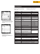

Input Characteristics Ranges Accuracy
Input impedance 1 MΩ, 20 pF
Voltage rating 600 Vrms, CAT III
Volt/Amps/Hertz
True-rms voltage (AC+DC) 5.000 V, 50.00 V, 500.0 V, 1250 V* ± (1 % + 10 counts)
True-rms current (AC+DC) 50.00 A, 500.0 A, 5.000 kA, 50.00 kA, 1250 kA ± (1 % + 10 counts)
Frequency 10.0 Hz to 15.0 kHz ± (0.5 % + 2 counts)
CF Crest Factor 1.0 to 10.0 ± (5 % + 1 count)
Power
W, VA, VAR Reactive Power 250 W 2.50 kW, 25.0 kW, 250kW, 2.50 MW, ± (2 % + 6 counts) Total Power
1-phase and 3-phase, 3 25 MW, 250 MW, 625 MW, 1.56 GW ± (4 % + 4 counts) Fundamental
conductor balanced loads Power
PF Power Factor 0.00 to 1.00 ± 0.04
DPF Displacement Power Factor 0.00 to 0.25 not specified
0.25 to 0.90 ± 0.04
0.90 to 1.00 ± 0.03
Hz Frequency fundamental 40.0 to 70.0 Hz ± (0.5 % + 2 counts)
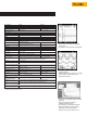
Harmonics
Volts, Amps, Watts Fundamental V, A ± (3 % + 2 counts),
W ± (5 % + 2 counts)
2 to 31st Harmonic V, A ± (5 % + 3 counts),
W ± (10 % + 10 counts)
32 to 51st Harmonic V, A ± (15 % + 5 counts),
W ± (30 % + 5 counts)
Frequency of fundamental 40 Hz to 70 Hz ± 0.25 Hz
Phase Volt & Amps (between Fund. & Harmonic) 2nd (± 3°) … 51st (± 15°)
Watts (between Volt Fund. & Amps
Harmonic ) Fund (± 5°) … 51st (± 15°)
K-Factor (Amps & Watts) 1.0 to 30.0 ± 10 %
THD 0.00 to 99.99 ± (3% + 8 counts)
Sags & Swells
Recording times (selectable) 4 min to 16 days
Vrms actual, Vrms max, 5.000 V, 50.00 V 500.0 V, 1250 V* Readings ± (2 % +10 counts)
min (AC + DC) Cursor readings ± (2 % + 12 counts)
Cursor Readings Average ± (2 %
+10 counts)
Arms actual, Arms max, 50.00 A, 500.0 A, 5.000 kA, 50,00 kA
min (AC + DC)
Recording
Rec
ording times (selectable)
4 min to 1
6 days
P
arameters
Choose one or two parameters from one of the g
roups below
V/A/Hz Line Voltage, Current, Frequency
Power Watts, VA, VAR, PF, DPF, Frequency
Harmonics THD, Volts (Fund. & Harmonic), Amps(F&H) Watts(F&H) Freq.(H), %(H) of total, Phase(H), KF
Ohms Ohms, Diode, Continuity, Capacitance
Temperature °C or °F
Scope DC Voltage, DC Current, AC Voltage, AC Current, Frequency, Pulse Width + or -,
Phase, Duty c
ycle + or -, P
eak max, P
eak min, P
eak min-max, Crest F
actor
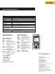
Tr
ansients
Minimum pulse w
idth
40 ns
Useful bandw
idth input
D
C to 1 M
Hz (w
ith test leads TL24)
Numb
er of transients
40
V
oltage threshold settings
20 %, 50 %, 1
00 %, 200 % ab
ove or b
elow reference signal
Referenc
e sig
nal
After S
T
ART, the Vrms and frequency of the signal are measured. From these
data a pure sinewave is calculated as reference for threshold setting.
Vpeak min, Vpeak max at cursor 10 V, 25 V, 50 V, 125 V, 250 V, 500 V, 1250 V ± 5 % of full scale
*Rated 600 V CAT II
Specifications
Accuracies are stated as ± (percentage of
reading + counts) without probes unless
otherwise noted.
Specifications are valid for signals with a
fundamental between 40 and 70 Hz.
• Measurements are always automatically
recorded to instantly show changes over time
• Use cursors to read time and date of sags
and swells
• Catch voltage transients and waveform
distortion down to 40 nS
• Catch and save up to 40 transients
• Correlate the cause of transients with time
and date stamps