914X Series Field Metrology Well User’s Guide Revision 7A1901-EN
Limited Warranty & Limitation of Liability Each product from Fluke Corporation, Hart Scientific Division (“Hart”) is warranted to be free from defects in material and workmanship under normal use and service. The warranty period is one year for Field Metrology Wells. The warranty period begins on the date of the shipment. Parts, product repairs, and services are warranted for 90 days.
Table of Contents 1 Before You Start........................................................................1 1.1 1.2 1.3 1.4 Introduction................................................................................................ 1 Unpacking................................................................................................. 2 Symbols Used............................................................................................ 3 Safety Information..................................
5 Maintenance............................................................................35 5.1 Field Metrology Well Performance Analysis............................................
Tables Table 1 Symbols used......................................................................................... 3 Table 2 Base Unit Specifications...................................................................... 13 Table 3 -P Option Specifications .....................................................................
Figures Figure 1 Clamp-on ferrite installation.................................................................. 9 Figure 2 914X Field Metrology Well.................................................................. 18 Figure 3 Display panel and keys ..................................................................... 20 Figure 4 914X display....................................................................................... 21 Figure 5 9142 power panel...................................................
Before You Start Introduction 1 Before You Start 1.1 Introduction Field Metrology Wells (9142, 9143, and 9144) are designed to be reliable, stable heat sources that can be used in the field or laboratory. They offer accuracy, portability, and speed for nearly every field calibration application. The instruments have been designed with the field user in mind and are easy to use while maintaining stability, uniformity, and accuracy comparable to some laboratory instruments.
914X Field Metrology Wells Unpacking sensors and devices. Before use, the user should be familiar with the warnings, cautions, and operating procedures of the calibrator as described in the User’s Guide. 1.2 Unpacking Unpack the instrument carefully and inspect it for any damage that may have occurred during shipment. If there is shipping damage, notify the carrier immediately.
Before You Start Symbols Used 9144 9144 Field Metrology Well 9144-INSX Insert (X=A, B, C, D, E, or F) ●● Power Cord ●● RS-232 Cable ●● User Guide ●● Technical Manual CD ●● Report of Calibration and calibration label ●● 6-pin DIN Connector (-P model only) ●● Test Lead Kit (-P model only) ●● Clamp-on ferrites (3) [-P model only] ●● Tongs (insert removal tool) ●● 9930 Interface-it Software and User’s Guide If all items are not present, contact an Authorized Service Center (see Section 1.
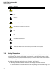
914X Field Metrology Wells Safety Information Symbol Description Electric Shock Fuse PE Ground Hot Surface (Burn Hazard) Read the User’s Guide (Important Information) Off On Canadian Standards Association C-TICK Australian EMC mark The European Waste Electrical and Electronic Equipment (WEEE) Directive (2002/96/ EC) mark. 1.4 Safety Information Field Metrology Wells are designed in accordance with IEC 61010-1, IEC 61010-2-010 and CAN/CSA 22.2 No 61010.1-04.
Before You Start Safety Information 1.4.1 Warnings To avoid personal injury, follow these guidelines. GENERAL DO NOT use this instrument in environments other than those listed in the User’s Guide. Inspect the instrument for damage before each use. Inspect the case. Look for cracks or missing plastic. DO NOT use the instrument if it appears damaged or operates abnormally. Follow all safety guidelines listed in the User’s Guide. Calibration equipment should only be used by trained personnel.
914X Field Metrology Wells Safety Information Never touch the probes to a voltage source when the test leads are plugged into the current terminals. Select the proper function and range for each measurement. Disconnect the test leads before changing to another measure or source function. DO NOT operate the Field Metrology Well around explosive gas, vapor, or dust. DO NOT operate instrument at orientations other than upright.
Before You Start Safety Information If supplied with user accessible fuses, always replace the fuse with one of the same rating, voltage, and type. Always replace the power cord with an approved cord of the correct rating and type. HIGH VOLTAGE is used in the operation of this equipment. SEVERE INJURY or DEATH may result if personnel fail to observe safety precautions. Before working inside the equipment, turn power off and disconnect power cord.
914X Field Metrology Wells CE Comments DO NOT allow the probe sheath or inserts to drop into the well. This type of action can cause a shock to the sensor and affect the calibration. The instrument and any thermometer probes used with it are sensitive instruments that can be easily damaged. Always handle these devices with care. DO NOT allow them to be dropped, struck, stressed, or overheated. DO NOT operate this instrument in an excessively wet, oily, dusty, or dirty environment.
Before You Start Authorized Service Centers we recommend that the clamp-on ferrites provided be used on the cables of probes attached to the readout, especially if the product is used near sources of EM interference such as heavy industrial equipment. To attach a ferrite to a probe cable, make a loop in the cable near the connector and clamp the ferrite around half of the loop as shown in the diagram. The ferrite can be easily snapped open and moved to a new probe when needed.
914X Field Metrology Wells Authorized Service Centers Fluke Nederland B.V. Customer Support Services Science Park Eindhoven 5108 5692 EC Son NETHERLANDS Phone: +31-402-675300 Telefax: +31-402-675321 E-mail: ServiceDesk@fluke.nl Fluke Int’l Corporation Service Center - Instrimpex Room 2301 Sciteck Tower 22 Jianguomenwai Dajie Chao Yang District Beijing 100004, PRC CHINA Phone: +86-10-6-512-3436 Telefax: +86-10-6-512-3437 E-mail: xingye.han@fluke.com.cn Fluke South East Asia Pte Ltd.
11
Specifications and Environmental Conditions Specifications 2 Specifications and Environmental Conditions 2.1 Specifications Table 2 Base Unit Specifications Base Unit Specifications 9142 9143 9144 –25 °C to 150 °C (-13 °F to 302 °F) 33 °C to 350 °C (91 °F to 662 °F) 50 °C to 660 °C (122 °F to 1220 °F) Display Accuracy ± 0.2 °C Full Range ± 0.2 °C Full Range ± 0.35 °C at 50 °C ± 0.35 °C at 420 °C ± 0.5 °C at 660 °C Stability ± 0.01 °C Full Range ± 0.02 °C at 33 °C ± 0.02 °C at 200 °C ± 0.
914X Field Metrology Wells Specifications Base Unit Specifications Weight 9142 9143 9144 8.16 kg (18 lbs) 7.3 kg (16 lbs) 7.7 kg (17 lbs) Power Requirements 100 V to 115 V (± 10 %) 50/60 Hz, 635 W 230 V (± 10 %) 50/60 Hz, 575 W 100 V to 115 V (± 10 %), 50/60 Hz, 1400 W 230 V (± 10%), 50/60 Hz, 1800 W System Fuse Ratings 115 V: 6.3 A T 250 V 230 V: 3.
Specifications and Environmental Conditions Environmental Conditions -P Specifications Built-in TC Thermometer Readout Accuracy Type J: ± 0.7 °C at 660 °C Type K: ± 0.8 °C at 660 °C Type T: ± 0.8 °C at 400 °C Type E: ± 0.7 °C at 660 °C Type R: ± 1.4 °C at 660 °C Type S: ± 1.5 °C at 660 °C Type M: ± 0.6 °C at 660 °C Type L: ± 0.7 °C at 660 °C Type U: ± 0.75 °C at 600 °C Type N: ± 0.9 °C at 660 °C Type C: ± 1.1 °C at 660 °C TC Millivolt Range –10 mV to 75 mV Voltage Accuracy 0.025 % of reading +0.
Quick Start Setup 3 Quick Start 3.1 Setup Note: The instrument will not heat, cool, or control until the “SET PT.” parameter is “Enabled”. Place the calibrator on a flat surface with at least 6 inches of free space around the instrument. Overhead clearance is required. DO NOT place under a cabinet or structure. Plug the instrument power cord into a mains outlet of the proper voltage, frequency, and current capability (see Section 2.1 Specifications on page 13 for power details).
914X Field Metrology Wells Parts and Controls Figure 2 914X Field Metrology Well 3.2 Parts and Controls This section describes the exterior features of the Field Metrology Well. All interface and power connections are found on the front of the instrument (see Figure 2).
Quick Start Parts and Controls 3.2.1 Display Panel Figure 3 on next page shows the layout of the display panel. Display (1) The display is a 240 x 160 pixel monochrome graphics LCD device with a bright LED backlight. The display is used to show current control temperature, measurements, status information, operating parameters, and soft key functions. udlr Arrow Keys (2) The Arrow Keys allow you to move the cursor on the display, change the display layout, and adjust the contrast of the display.
914X Field Metrology Wells Parts and Controls Block Temperature Indicator (10) [Patent Pending] The Block Temperature Indicator lamp allows users to know when the block temperature is safe (50°C to 60°C) to remove inserts or move the Field Metrology Well. The indicator light is lit continuously once the block has exceeded approximately 50°C (varies 50°C to 60°C). The indicator light stays lit until the block cools to less than approximately 50°C.
Quick Start Parts and Controls Stability Status (4) On the right hand side of the screen, you will find a graph displaying the current status of the stability of the Field Metrology Well. Heating/Cooling Status (5) Just below the stability graph there is a bar graph that will indicate HEATING, COOLING, or CUTOUT. This status graph indicates the current level of heating or cooling if the instrument is not in cutout mode.
914X Field Metrology Wells Parts and Controls 3.2.3 Power Panel The following are found on the lower front panel of the instrument (see Figures 5 and Figure 6 on opposite page). Power Cord Plug (1) The power supply cord attaches to the lower front power panel. Plug the cord into an AC mains supply appropriate for the voltage range as specified in the specifications tables.
Quick Start Parts and Controls Figure 5 9142 power panel Figure 6 9143 and 9144 power panel 23
914X Field Metrology Wells Parts and Controls 3.2.4 -P Option Panel (-P models only) The –P (process version) panel is the readout portion of the instrument and is only available with –P models.
Quick Start Parts and Controls Probe Connector 1 2 6 5 3 4 Shield RTD Sensor Figure 8 Probe connector wiring A two-wire probe can also be used with the reference thermometer. It is connected by attaching one wire to both pins 1 and 2 of the plug and the other wire to both pins 4 and 5. If a shield wire is present, it should be connected to pin 3. Accuracy may be significantly degraded using a two-wire connection because of lead resistance.
914X Field Metrology Wells Languages Figure 9 Jumper locations for 3-wire and 2-wire connections Thermocouple (TC) Connector (4) The TC connector allows for the use of subminiature TC connectors (see CE Comments on page 8 for information on using clamp-on ferrites). Fuse (5) Fuse for the 4-20 mA circuit. Always replace with a fuse of the appropriate rating (see Section 2.1 Specifications on page 13). 3.
Quick Start Languages Figure 10 Steps to language selection 3.3.2 Reset to English Language If you are in a language and need a short cut exit, press F1 and F4 simultaneously to reset the display to English. To reset to your originally selected language after resetting to English, follow the steps in Figure 10 on this page. Note: The F1 and F4 English shortcut override is temporary.
Menu Structure Temp Setup Menu 4 Menu Structure 4.
914X Field Metrology Wells Prog Menu 4.2 Prog Menu 9142/9143/9144 MAIN MENU F1 TEMP SETUP F2 PROG MENU F1 RUN PROGram F2 RAMP/SOAK F4 INPUT SETUP (-P only) TEST STATUS:
Menu Structure Prog Menu 4.2.1 Switch Test Parameters SWITCH TEMP The SWITCH TEMP parameter is the nominal change temperature of the switch. UPPER TEMP The UPPER TEMP parameter is the temperature during a cycle at which the Field Metrology Well begins to heat or cool at the rate specified in “Scan Rate” found in MAIN MENU|TEMP SETUP|SETUP|SCAN RATE.
914X Field Metrology Wells Prog Menu RUN. Press Enter and the instrument will engage and start the test within a few seconds. Exit to the main screen to view the test progress, refer to the Menu Structure. When the switch resets, the test completes and the values of the switch OPEN, switch CLOSE, and switch BAND are displayed for the user to record. The values may also be recorded internally in the instrument by selecting the option to record the data (-P model only).
Menu Structure System Menu 4.
914X Field Metrology Wells Input Setup (-P only) 4.
Maintenance Field Metrology Well Performance Analysis 5 Maintenance The Field Metrology Well has been designed with the utmost care. Ease of operation and simplicity of maintenance have been a central theme in the product development. With proper care, the instrument should require very little maintenance. Avoid operating the instrument in an oily, wet, dirty, or dusty environment. Operating the instrument in a draft-free environment facilitates improved performance of the instrument.
914X Field Metrology Wells Field Metrology Well Performance Analysis Accuracy Drift The display temperature of the instrument will drift over time. This is due to a variety of factors affecting the temperature control PRT. Any PRT is subject to changes depending on how it is used and the environment it is used in. This is no different for any PRT in a calibration application. In addition, manufacturing variables in the sensing element itself can result in greater or lesser impact from use and environment.