
User's Manual


10 Fluke Corporation Concerned about arc-flash and electric shock?
Crystal windows
With a crystal infrared window, the R + A + T
= 1 effects are multiplied with respect to the
camera by a factor of two.
These additional signals can be simplified
and compensated for by making some practical
assumptions based on real life applications.
The first point to understand when investigat-
ing transmission is that the apparent error in
the camera will not always be a negative, i.e.
the camera may read LOW or it may read HIGH
depending upon contributing factors.
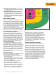
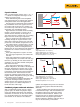
Figure 9 shows an infrared camera scanning
through a crystal window at a target. Let us
assume that the emissivity of the target is 1.
The camera shows a positive error: it is reading
higher than the actual target temperature.
Figure 10 shows the same infrared camera
scanning through the crystal window at the
same target. This time however, the optic tem-
perature is at the ambient temperature of 30 °C
The camera shows a negative error: it is read-
ing lower than the actual target temperature.
At first glance, these two examples seem to
indicate that the error associated with electrical
inspection via a window cannot be compen-
sated for:
•
If the optic temperature is equal to or lower
than the target temperature, the camera will
read low.
•
If the optic temperature is higher than the
target temperature, the camera will read high.
However, by thinking in more detail about the
application, we can make sensible assumptions
that remove the latter.
Since unpowered switchgear is sitting at
ambient temperature, the whole of the body and
internals—including the window optic—is also
at ambient temperature. When the switchgear
is energized, current begins to flow through the
internal conductors. This increases the tem-
perature of potential targets above that of the
original ambient temperature, leaving the casing
(and window optic) at ambient.
Since scanning de-energized equipment will
not provide meaningful results, it is safe to
assume that the outer casing and hence the
window optic is at a similar temperature or
lower than that of the target.
Combined polymer and mesh windows
With a combination product such as a mesh/
polymer optic, the mesh and polymer compo-
nents have differing absorption and reflection
coefficients. In this case, we can never account,
in a repeatable manner, for the infrared radia-
tion incident on the detector. The reflected
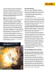
Figure 8. Additional signals resulting from the use of a window.
Figure 9. An infrared camera scanning through a crystal window at a
target.
Target Temperature = 50 °C (122 °F)
Ambient Temperature = 30 °C (86 °F)
Window Optic Temperature = 60 °C (140 °F)
Indicated Temperature = 55 °C (131 °F)
Figure 10. An example of negative error.
Target Temperature = 50 °C (122 °F)
Ambient Temperature = 30 °C (86 °F)
Window Optic Temperature = 30 °C (86 °F)
Indicated Temperature = 45 °C (113 °F)
Panel
Target
Panel
Target
Optic
Optic
quotient is multiplied many times over because
of the mesh and polymer material reflectivity
difference.
Another problem with scanning through mesh
is the deflection angle. This term describes the
inconsistent effect of the mesh with respect
to reflected infrared radiation. Similar to the
faceted faces used on modern stealth aircraft,
combined mesh and polymer optics deflect
infrared radiation in different paths that may or
may not be detected by an IR camera.