
User's Manual


4 Fluke Corporation Concerned about arc-flash and electric shock?
Inevitably, a serious arc flash will damage or
even destroy the affected equipment. This leads
to extensive downtime and expensive replace-
ment and repair.
An incident may also represent a failure on
the part of the employer to comply with indus-
try guidelines and regulations. This could result
in a fine, litigation fees, increased insurance
costs, expensive legal actions and accident
investigations.
Standards and guidelines
The potential dangers of an arc flash can
be reduced by following the relevant safety
guidelines and using personal protective
equipment PPE.
In the USA, the following OSHA and NFPA
regulations apply to personnel working with
energized electrical equipment:
•
NFPA 70 (“National Electric Code”)
•
NFPA 70E (“Standard for Electrical Safety in
the Workplace”)
•
OSHA Standards 29-CFR, Part 1910 (S)
1910 333
•
OSHA Standards 29-CFR, Part 1926 Subpart K
•
IEEE Standard 1584-2002, (“Guide for
Performing Arc Flash Hazard Calculations.”)
Many other countries have their own broadly
similar standards and regulations. For example,
Canada’s regulations can be found in CSA Z462.
In the UK, compliance with EAWR (Electricity at
Work Regulations) 1989, section 5 is required.
NFPA 70E—the safety standard
NFPA 70E defines the safe parameters for
personnel working on electrical equipment.
Although adherence is not a legal require-
ment, the standard provides a benchmark for
most industries to demonstrate compliance
with OSHA’s General Duty clause. An employer
adopting the guidelines offered in NFPA 70E
demonstrates a clear commitment to safe work-
ing practices and the protection of employees
from shock and arc flash hazards.
According to the standard, if personnel will be
operating in the presence of energized equip-
ment, then certain safety considerations are
applicable. 70E recognizes that there may be
the potential for arc flash and arc blast even
when conductors are not exposed. Qualified
personnel responsible for the work must:
•
Conduct an arc flash hazard analysis
•
Implement qualified and general worker
safety training based on the results
•
Establish shock and flash protection
boundaries
•
Provide protective clothing and personal
protective equipment to ANSI standards
•
Put warning labels on equipment
•
Authorize the job with a ‘live work’ permit
Steps for an arc flash hazard analysis
Section 4 of IEEE 1584-2002 outlines a 9-step
procedure for arc flash hazard analysis. The
purpose of this analysis is to “identify the flash
protection boundary and the incident energy at
assigned working distances...”
The nine steps are:
1. Collate system data. Collect system and
installation information for a detailed short
circuit assessment. You will need to describe
the system and the arrangement of its
components in a one-line drawing with
nameplate specifications for each device
and the lengths and cross-sectional areas of
interconnecting cables.
2. Consider all modes of operation. Examine
the different ways that the system operates
and how this may affect the risks and magni-
tudes of arc hazards.
3. Calculate bolted fault currents. Using the
data gathered in the first two steps, calculate
the highest bolted fault current expected to
flow during any short circuit.
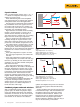
4. Calculate arc fault currents. During an arc
fault, the current flow is normally lower than
that of a bolted fault in the same equipment
because of the added impedance of the arc.
For example, for a bolted fault of 40 kA at
480 V the corresponding arc fault would be
expected to yield about 20 kA. IEE 1584-
2002 provides formula for estimating arc fault
currents.
5. Determine protective device characteris-
tics and arc durations. Estimate how over
current protection devices will react during
an arc fault. These may react more slowly,
extending the duration and power of the arc
flash. Through the analysis, it may be possi-
ble to reduce the arc flash hazard and lower
the PPE requirement by replacing existing
circuit breakers. For example, modern, cur-
rent-limiting fuses may considerably reduce
arc flash energies by reacting more rapidly
and at lower over current values.
6. Document system voltages. Establish bus
gaps and operating voltages.
7. Estimate working distances. Determine the
distances from arc fault sources to a worker’s
face and chest. Although hands and arms
may be closer to any incident, injuries are
unlikely to be life-threatening.