
User's Manual


6 Fluke Corporation Concerned about arc-flash and electric shock?
An important point here is that the flash
protection boundary and the rules govern-
ing access within it take precedence over the
shock hazard boundaries. So, for example, if
the flash protection boundary is greater than the
limited approach boundary then no unqualified
person can be permitted in the limited approach
area and even qualified workers must wear
appropriate arc-resistant PPE here.
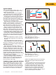
You can determine the flash protection bound-
ary for an electrical system using the calculating
methods contained in NFPA 70E and IEEE Std
1584. The equations are based on the voltage
level, fault level and the trip time of the protec-
tive device.
The conditional flash protection boundary
is 48 inches for low voltage (<600 V) systems
where the total fault exposure is less than 100k
amperes-seconds (fault current in amperes mul-
tiplied by the upstream device clearing time in
seconds). On such a system, a qualified person
who works closer than 48 inches from the live
components must wear PPE for arc-flash protec-
tion including flame-resistant (FR) clothing. Of
course, further PPE may be necessary for pro-
tection against electric shock according to the
location of the shock protection boundaries.
Please refer to IEEE 1584 for comprehensive
calculation methods for a wide range of electri-
cal systems; the procedures describe calculation
methods for equipment with voltages in the
range: 208 V to 15 kV.
Choosing the right PPE
As an option to incident energy analysis to
assist in the choice of appropriate personal
protection equipment for arc flash hazards, NFPA
70E defines five hazard risk categories (HRCs):
0, 1, 2, 3, and 4.
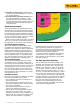
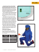
Figure 3. The Flash protection boundary takes precedence over the
shock hazard boundaries.
Hazard/Risk
Category
APTV rating
(cal/cm²)
0 N/A
1 4
2 8
3 25
4 40
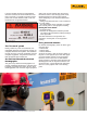
Figure 4. Category 4 PPE.
Copyright image courtesy of Salisbury by Honeywell