
User's Manual

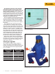
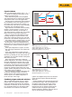

9 Fluke Corporation Concerned about arc-flash and electric shock?
How can infrared windows help?
An infrared window provides a solid barrier
between the thermographer and the live con-
ductors. By careful design, it is possible to not
only to reduce the trigger effects of an arc but
also provide the thermographer with a far safer
working environment.
Thermography windows are relatively new
technology, so there is no specific standard that
relates to construction and testing. However,
since they are invariably installed close to arc
flash hazards, it is important that windows can
withstand not only an arc flash incident but also
the rigors of their environment and normal day-
to-day operation.
In the United States, Canada and Europe,
there are differing standards associated with
testing equipment to be deemed “arc-resistant”,
specifically: ANSI C37.30.7 (North America),
EEMACS G14-1 (Canada), IEC62271 (Europe).
These standards are manifestly different and
cannot be translated from one to another.
For example, a product tested to IEC62271 in
Europe cannot be claimed to be suitable for
North American ANSI C37.20.7 nor Canadian
EEMACS G14-1.
End-use requirements vary considerably so
testing and certification needs to be generic in
order to provide an all-round product suitable
for use in most if not all applications.
Manufacturers tend to design viewing panes
to withstand accidental impacts from untrained
personnel in transit rather than the com-
bined pressure piling and sudden temperature
increase effects of an internal electric arc.
Infrared windows, on the other hand, are con-
structed of crystal optic materials designed to
better protect the infrared thermographer under
an arc-flash condition during scheduled, peri-
odic inspection of the internal equipment.
Inspection devices may also feature locking
security covers. This ensures only a trained and
authorized person can remove and complete
an inspection or scan. It also protects the optic
material from day-to-day impacts and offers
further arc-flash protection. Properly constructed
cover designs are manufactured from materials
that offer substantially similar properties as the
original panel wall knock-out—National Electric
Code 110.12(A).
Selecting the correct material
There are numerous materials that can “trans-
mit” infrared radiation from low cost thin film
plastics used for home intruder alarm systems to
germanium optics for military imaging.
Unfortunately, there are not many materials
suitable for the task of permanent installation
into electrical equipment due to the combined
temperatures and pressure experienced during
an arc-flash.
Typically, infrared windows are manufactured
from a crystal optic material that allows infra-
red and visual inspection via the same product.
This material choice, if designed and imple-
mented correctly, can withstand an electric
arc and provide a measure of protection to the
thermographer.
Conversely, thin film polymers can transmit IR
in certain wavelengths—although actual trans-
mission is poor—however the polymer itself
cannot withstand the temperature and pressure
of an electric arc and hence could become a
dangerous molten projectile.
The most widely used optic material is that of
crystal. A properly coated crystal optic can:
1. Maintain IR camera flexibility
2. Allow visual inspection
3. Enable corona inspection
4. Be arc-resistant
Understanding transmission
Infrared window transmission is a commonly
misused term when it comes to obtaining a
measurement. Since no material is 100 %
transmissive, other factors come into play when
attempting to correct for the apparent error.
As any good thermographer knows from
training:
Reflection + Absorption + Transmission = 1
A thermographer must think of the window and
thermal imager as an integrated system.
A little known fact is that the spectral range of
an infrared camera varies from one model to the
next. This is down to the individual “Switch-on,
Switch-off” parameter of the infrared detector.
For example, one longwave camera may have a
working spectral response of 8.1 µm to 13.9 µm;
the next unit to leave the line may operate at
7.9 µm to 13.5 µm. When this differing spectral
response on the detector is mapped against an
IR window product, the apparent “transmission”
changes as a function of the detector/window
relationship.
With a crystal window, this relationship is
relatively straightforward to understand as the
“route” through the optic is consistent. However,
when mesh is introduced into the equation,
the relationship becomes more complex still.
The route through the combined polymer/mesh
optic is confused and inconsistent resulting in a
vignette problem (a vignette effect is known to
photographers as the way a photograph fades
towards its edges—often used for effect, it can
be an unintentional result of the optical limita-
tions of the camera’s lens). Even obtaining a
good image consistently is a challenge when
attempting to scan through mesh.