
Datasheet

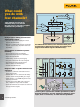
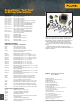

AC to DC
conversion
Mains
supply
Mechanical
output
Motor (load) Cable interface
DC to AC converter
DC lter
and buffer
bus
voltage
L1
T3
L2
T2
L3
Gnd
T1
+Vdc
-Vdc
T3
T2
T1
Input
Safety control
Feedback
Analog/Digital
Output
Condition
Transducers
Measurements’
Process/Display
Power Supply
Analog
Digital
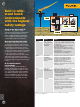
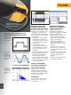
Easily diagnose timing-related issues
with multiple signals
• Real-time inspection of multiple related
signals simultaneously
• Measure a combination of input and output
signals, system safety interlocks and feed-
back loops
Find problems in industrial systems
including:
• Circuit voltage/current overloading
• Attenuation/input impedance mismatch
• Signal fluctuation/drift
• Conditioning circuits signal integrity
• Test point verification for critical signals
• Input/output/feedback timing issues
• Induced noise and disturbances
• Random shutdowns/reset
Diagnose VSDs* or power inverters and
converters
• Harmonics, transients and loads in three-
phase power input
• Troubleshoot dc to ac converters for faulty
control circuits or output IGBT gate stages
• Cable interface—test PWM output for reflec-
tions and transients
• Accurately measure IGBT pulse edge rise-
time, amplitude and peak of relections
• Vpwm measurement to measure the effective
voltage on drive outputs
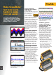
What could
you do with
four channels?
Take multiple measurements
simultaneously to track down
the root cause of your most complex
troubleshooting challenges.
In three-phase systems like variable speed drives, UPS or
back-up generators, use four channels to diagnose power
input, dc to ac converters, or cable interface problems.
For industrial electronics, four channels allow you to
perform three-dimensional testing, measuring input,
output and feedback signals simultaneously.
*Variable Speed Drive
5