
User's Manual


5 220A
Instruction Manual
4-2
4-2. Service Information
The 5220A is warranted for a period of 1-year upon delivery to the original purchaser.
The warranty is located on the back of the title page.
Factory authorized calibration and service for each Fluke product is available at various
worldwide locations. A complete list of these service centers is included in Section 7 of
this manual. If requested, an estimate will be provided to the customer before work is
begun on instruments that are beyond the warranty period.
4-3. General Maintenance
4-4. Cleaning
Clean the 5220A periodically to remove dust, grease, and other contamination. Use the
following procedure:
1. Clean the front panel and case with a soft cloth dampened with a mild solution of
detergent and water.
2. Clean the surface of the PCBs using clean, dry air at low pressure (<20 psi). If grease
is encountered, spray with Freon T.F. Degreaser and remove grime with dry, low-
pressure air.
4-5. Air Filter Maintenance
Periodically inspect the air filter on the rear panel for dirt and contaminants. If cleaning is
required, use the following procedure:
1. Disconnect the 5220A from line power.
2. Remove the two screws from the filter housing and gently pull the filter assembly
from the unit.
3. Clean the filter using either low-pressure air or a mild solution of detergent and
water.
4. Dry (if necessary) and reinstall the filter.
4-6. Access Information
The 5220A is a modular instrument that can be easily disassembled by sections.
Procedures for section disassembly are given in the following paragraphs. Some
procedures require the completion of previous procedures in the disassembly process.
When this occurs, the previous procedure will be referenced, but not repeated.
WWarning
To avoid electrical shock hazard, disconnect he 5220A from line
power before attempting any of the following disassembly
procedures.
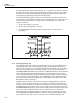
Reassembly of the instrument is accomplished by logically reversing the disassembly
procedure. Before installing the top covers on the unit, make a visual comparison with
Figure 4-1 to ensure the presence of all assemblies, jumpers, and fuses.