
User's Manual


5 220A
Instruction Manual
4-18
Table 4-5. Replacement Resistors for R13
Corrected DVM Indication (mV dc) Selected Value for R13 (Ω) Fluke Part Number
102.000 to 101.800 1740 Ω 357756
101.800 to 101.600 1500 Ω 376947
101.600 to 101.400 1282 Ω 330472
101.400 to 101.200 1100 Ω 347161
101.200 to 101.000 900 Ω 460519
101.000 to 100.800 698 Ω 289330
100.800 to 100.600 499 Ω 289256
100.600 to 100.400 301 Ω 289173
100.400 to 100.200 100 Ω 357400
100.200 to 100.000 0 Ω NA
4-41. Troubleshooting
hCaution
Static discharge can damage MOS components contained in
the 5220A. To prevent this possibility use the following
precautions when troubleshooting and/or repairing the unit.
• Never remove, install, or otherwise connect, or disconnect PCBs and/or components
without disconnecting, the unit from line power.
• Perform all repairs at a static-free work station.
• Do not handle ICs or PCBs by their connectors.
• Use static ground straps to discharge repair personnel.
• Use conductive foam to store replacement or removed ICs.
• Remove all plastic, vinyl, and Styrofoam products from the work area.
• Use a grounded soldering iron.
A troubleshooting guide for the 5220A is given in Table 4-4 and 4-5. The guide is in the
form of a tabular flow chart and is recommended for use in isolating a mainframe
malfunction to the PCB (board) level. Details necessary to troubleshoot faulty PCBs to
the component level can be derived from the schematic diagrams given in Section 8, and
the theory of operation in Section 3.
When using the troubleshooting guides, the following notes apply:
• Do not start in the middle of the procedure. Any given step assumes that the previous
steps have been completed. Complete Table 4-4 before going on to Table 4-5.
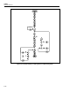
• All measurements using external test equipment are made at test points on the various
PCB assemblies. See Figure 4-3 for test point location/identification.