® 2640A/2645A NetDAQ Networked Data Acquisition Unit Users Manual PN 942623 May 1994, Rev 2 11/96 © 1994, 1995, 1996 Fluke Corporation, All rights reserved. Printed in U.S.A. All product names are trademarks of their respective companies.
LIMITED WARRANTY & LIMITATION OF LIABILITY Each Fluke product is warranted to be free from defects in material and workmanship under normal use and service. The warranty period is one year and begins on the date of shipment. Parts, product repairs and services are warranted for 90 days.
PCaution This is an IEC safety Class 1 product. Before using, the ground wire in the line cord or rear panel binding post must be connect to an earth ground for safety. Interference Information This equipment generates and uses radio frequency energy and if not installed and used in strict accordance with the manufacturer’s instructions, may cause interference to radio and television reception.
SAFETY TERMS IN THIS MANUAL This instrument has been designed and tested in accordance with IEC publication 1010-1, Safety Requirements for Electrical Measuring, Control and Laboratory Equipment. This Users Manual contains information, warnings and cautions. Use of this equipment in a manner not specified herein may impair the protection provided by the equipment. This instrument is designed for IEC 1010-1 Installation Category II use.
DC POWER SOURCE The instrument may also be operated from a 9V to 16V dc power source when either the rear panel ground binding post or the power cord grounding conductor is connected properly. USE THE PROPER FUSE To avoid fire hazard, for fuse replacement use only a 1/4 ampere, 250V non-time delay line fuse.
Table of Contents Chapter 1 Title Overview ........................................................................................... 1-1. Introduction .......................................................................................... 1-2. Instrument Features and Capabilities ................................................... 1-3. Analog Channels .............................................................................. 1-4 Computed Channels ..................................................
2640A/2645A NetDAQ Users Manual 2 Preparing for Operation .................................................................. 2-1. Introduction.......................................................................................... 2-2. Instrument Preparation......................................................................... 2-3. Unpacking and Inspecting the Instrument ....................................... 2-4. Positioning and Rack Mounting ......................................................
Contents (continued) 3 2-44. Setting Host Computer Networking Parameters .............................. 2-45. Installing NetDAQ Logger............................................................... 2-46. Installing NetDAQ Logger with Trumpet.................................... 2-47. Changing from an Isolated Network to a General Network ........ 2-48. Installing Trend Link for Fluke (Optional) ...................................... 2-49. Testing and Troubleshooting.........................................
2640A/2645A NetDAQ Users Manual 3-35. 3-36. 3-37. 3-38. Default Configuration Settings ............................................................ Using Configuration Lockout .............................................................. Saving an Instrument’s Configuration as a Text File. ......................... Configuring the netdaq.ini File ............................................................ 3-27 3-28 3-28 3-29 4 Operating NetDAQ Logger for Windows ......................................
Contents (continued) 6 5-13. Exporting Trend Link Data Files ..................................................... 5-14. Deleting Old Trend Link Files ......................................................... 5-15. Getting the Right Look for Your Trend Link Chart ............................. 5-16. Using the Trend Link Control Bar ................................................... 5-17. Using the Trend Link Menus ........................................................... 5-18.
2640A/2645A NetDAQ Users Manual 6-29. 6-30. 6-31. 6-32. 6-33. 6-34. 6-35. 6-36. 6-37. 6-38. 6-39. Totalizer Sensitivity Test ............................................................ Master Alarm Output Test............................................................... Trigger Input Test ............................................................................ Trigger Output Test ......................................................................... Calibration...................................
List of Tables Table 1-1. 2-1. 2-2. 2-3. 2-4. 2-5. 2-6. 3-1. 6-1. 6-2. 6-3. A-1. A-2. A-3. A-4. A-5. A-6. A-7. A-8. A-9. A-10. A-11. A-12. A-13. A-14. A-15. A-16. A-17. A-18. A-19. A-20. Title Models, Options and Accessories ................................................................... Front Panel Key Descriptions ......................................................................... Annunciator Display Descriptions ..................................................................
2640A/2645A NetDAQ Users Manual A-21. A-22. A-23. A-24. A-25. A-26. A-27. A-28. A-29. A-30. A-31. A-32. A-33. A-34. A-35. A-36. A-37. A-38. B-1. B-2. I-1. I-2. 2640A Thermocouple Specifications ............................................................. 2640A Frequency Accuracy Specifications.................................................... 2640A Frequency Sensitivity Specifications.................................................. 2645A DC Voltage Measurement General Specifications .................
List of Figures Figure 1-1. 1-2. 1-3. 1-4. 2-1. 2-2. 2-3. 2-4. 2-5. 2-6. 2-7. 2-8. 2-9. 2-10. 2-11. 2-12. 2-13. 2-14. 2-15. 2-16. 2-17. 2-18. 2-19. 2-20. 2-21. 2-22. 2-23. 2-24. 2-25. 2-26. 2-27. Title 2640A/2645A NetDAQ Networked Data Acquisition Units .......................... 2640A/2645A Front Panel .............................................................................. Typical Front Panel Display During Scanning and Monitoring ..................... 2640A/2645A Rear Panel.......................
2640A/2645A NetDAQ Users Manual 2-28. 2-29. 2-30. 2-31. 2-32. 2-33. 3-1. 3-2. 3-3. 3-4. 3-5. 6-1. 6-2. 6-3. 6-4. 6-5. C-1. D-1. D-2. D-3. D-4. H-1. Viewing the Instrument Ethernet Address...................................................... Examples for Viewing the Ethernet Address.................................................. Preparing for Network Operation ................................................................... Interconnection Using 10Base2 (Coaxial) Wiring..............................
Chapter 1 Overview Contents 1-1. 1-2. 1-3. 1-4. 1-5. 1-6. 1-7. 1-8. 1-9. 1-10. 1-11. 1-12. 1-13. 1-14. 1-15. 1-16. 1-17. 1-18. 1-19. 1-20. 1-21. 1-22. 1-23. 1-24. 1-25. 1-26. 1-27. 1-28. 1-29. Introduction .......................................................................................... Instrument Features and Capabilities ................................................... Analog Channels .............................................................................. Computed Channels ..........
2640A/2645A NetDAQ Users Manual 1-2
Overview Introduction Introduction 1 1-1. The 2640A and 2645A NetDAQ Networked Data Acquisition Units are 20-channel front ends that operate in conjunction with NetDAQ Logger for Windows (hereafter known as NetDAQ Logger) to form a data acquisition system. The instruments measure dc volts, ac volts, Ohms, temperature, frequency, and dc current. Temperature measurements use thermocouples or resistance-temperature detectors (RTDs). To measure other parameters, use an appropriate transducer.
2640A/2645A NetDAQ Users Manual Instrument Features and Capabilities 1-2. The following describes the front and rear panels of the instrument and its capabilities (Figures 1-2 to 1-4). Primary, Secondary, and Annunciator Displays. Indicators and annunciators for operating mode, configuration, display, and data measurements.
Overview Instrument Features and Capabilities REM (Remote) Annunciator. Indicates the Host Computer and the Instrument are communicating on the network, i.e., the instrument is being operated remotely. SCAN (Scanning) Annunciator. Indicates the instrument is scanning. MON (Monitor) Annunciator. Indicates the instrument is monitoring a channel (in this example, analog channel 8). You can monitor a channel with or without instrument scanning. 1 1208 (Global Channel Number).
2640A/2645A NetDAQ Users Manual Ground Terminal. Connects mainframe to ground. Ethernet 10BaseT Connector. A RJ-45 connector that interfaces the instrument with a 10BaseT Twisted-Pair Ethernet network. The instrument automatically selects the active 10Base2 or 10BaseT connector. Universal Input Module. Directly wires 20 analog inputs (Channels 1 to 20) without need for external signal conditioning. Power Switch. Applies power to the instrument (ac or dc operation). AC Power Connector.
Overview Instrument Features and Capabilities Analog Channels 1 1-3. The analog channel (1 to 20) measurement connections are made via the Universal Input Module. External signal conditioning for the analog inputs is not necessary. The host computer configures all analog channels using NetDAQ Logger. Computed Channels 1-4. In addition to the 20 analog channels, the instrument provides an additional 10 computed channels (21 to 30) by processing analog channels and other computed channels.
2640A/2645A NetDAQ Users Manual Alarms 1-7. Two alarms, Alarm 1 and Alarm 2, can be applied to any configured channel. An alarm condition occurs when a measurement falls below a low alarm value or rises above a high alarm value. You can use alarms to trigger scanning (see “Alarm Triggering”) and to set a Digital I/O line to a logic low (see “Digital I/O” below). NetDAQ Logger displays and records alarm conditions.
Overview Instrument Features and Capabilities 1 overflows (reaching the maximum count), the display briefly shows OL (overload) and begins counting from zero again A totalizer input from contact closures increments on the “open” portion of the switch sequence close-open. To prevent switch contact “bounce” from triggering false readings, select the Totalizer Debounce feature. A totalizer input from voltage transitions increments during low-to-high voltage transitions with a nominal threshold of +1.4 volts.
40A/2645A NetDAQ Users Manual Master Alarm 1-13. Master Alarm is an instrument output line that is logic low (nominal +0.8V dc) for as long as any channel is in alarm while scanning is active. The connection uses the ALARM/TRIGGER I/O terminals MA and GND (Figure 1-4). This TTL output interfaces with external equipment such as warning lights, alarms, automatic shutdowns, and paging systems.
Overview NetDAQ Logger Features and Capabilities 1 You can combine Alarm Trigger with External Trigger and Interval Trigger. For example, set the Interval Trigger for 60 seconds (Interval 1) and the Alarm Trigger for 10 seconds (Interval 2). Scanning is at 60-second intervals except when a channel designated as an alarm trigger is in alarm, when scanning is at 10second intervals. NetDAQ Logger Features and Capabilities 1-17. NetDAQ Logger is the operating software for NetDAQ instruments.
2640A/2645A NetDAQ Users Manual operations refer to the instrument by BCN. NetDAQ Logger supports up to 20 instruments for operation. You cannot operate an instrument from more than one host computer at a time. Isolated Networks 1-19. An isolated network consists of only NetDAQ instruments and host computers. The advantages include simplified setup, faster network operation, and freedom from general network problems. Data throughput specifications are guaranteed only for isolated networks.
Overview Host Computer Requirements 1 Designate one instrument in the group as the Master and the others as Slaves. The Master controls scanning operations, including the scan intervals and method of scan triggering. You can create only one group instrument. Scanning and Logging 1-24. When a scan is triggered, the instrument scans the 20 analog channels and calculates the 10 computed channels. It stores the resulting time-stamped data in a scan record.
2640A/2645A NetDAQ Users Manual Host Computer Requirements 1-26. The host computer used for instrument operations must meet the following minimum requirements: • IBM PC with an Intel 386 microprocessor or greater, running Windows 95, Windows NT, or Windows 3.1. • Color VGA Monitor. • A Hard disk drive with 2 MB of free disk space. • A 1.44 Mbyte (3 1/2-inch) floppy disk drive. Options and Accessories 1-27.
Overview Options and Accessories Instrument Connector Set 1 1-28. The 2620A-100 is a complete set of input connectors: one Universal Input Module, one ALARM/TRIGGER I/O connector, and one DIGITAL I/O connector. A 2620A-100 Instrument Connector Set comes with each instrument. You can wire additional connector sets to allow quick interfacing to multiple wiring setups. Host Computer Ethernet Adapters 1-29. The 264XA-801, 264XA-802, and 264XA-803 are the recommended Ethernet adapters.
2640A/2645A NetDAQ Users Manual 1-16
Chapter 2 Preparing for Operation Contents Page 2-1. Introduction .......................................................................................... 2-3 2-2. Instrument Preparation ......................................................................... 2-3 2-3. Unpacking and Inspecting the Instrument........................................ 2-5 2-4. Positioning and Rack Mounting....................................................... 2-5 2-5. Connecting to a Power Source and Grounding...........
2640A/2645A NetDAQ Users Manual 2-29. Displaying the Totalizer Status ................................................... 2-26 2-30. Reviewing and Setting the Base Channel Number ..................... 2-27 2-31. Reviewing and Setting the Line Frequency ................................ 2-29 2-32. Reviewing and Setting the Network Type .................................. 2-31 2-33. Reviewing and Setting the General Network Socket Port .......... 2-36 2-34.
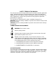
Preparing for Operation Introduction Introduction 2 2-1. This chapter describes how to prepare the instruments, host computers and network for operation, and how to test and troubleshoot system operation. Setting up your system requires the following steps (described in detail later in this chapter), performed in the order shown: • Instrument Preparation Unpacking and setting up the NetDAQ instrument. This section of the manual describes all the connections, controls, and indicators on the instrument.
2640A/2645A NetDAQ Users Manual NetDAQ NETWORKED DATA ACQUISITION UNIT 1 2 COMM DIO MON ENTER NetDAQ NETWORKED DATA AQUISITION UNIT NetDAQ DIO COMM MON NETWORKED DATA ACQUISITION UNIT ENTER COMM DIO MON ENTER NetDAQ NETWORKED DATA ACQUISITION UNIT COMM DIO MON ENTER Unpacking and Inspection 3 Positioning and Rack Mounting AC 4 DC Universal Input Module Connection Connecting to a Power Source 6 5 I/O Input/Output (I/O) Connections External Trigger (Group Instrument) 7 REVI
Preparing for Operation Instrument Preparation Unpacking and Inspecting the Instrument 2 2-3. Verify the contents of the shipping package against the checklist in the package. If any items are missing or damaged, report the problem immediately to your Fluke representative. Carefully remove the instrument from its shipping container, saving the packaging materials if possible. Inspect the rear rubber feet of the instrument.
2640A/2645A NetDAQ Users Manual Line Cord (AC Operation) OVERVOLTAGE CATEGORY II PER IEC 1010-1 107-264V MODEL: 2640A / 41A 2645A / 46A 50/60 Hz 15VA WARNING: TO AVOID ELECTRICAL SHOCK, DISCONNECT LINE CORD BEFORE REMOVING COVER ON / OFF ALARM/TRIGGER I/O DIGITAL I/O SERIAL PORT XMT RCV + MA TO TI 9-16V DC PWR 0 1 2 3 4 5 6 7 ETHERNET +30V LK NOT FOR CONNECTION TO PUBLIC TELEPHONE SYSTEMS MEETS VFG 243 / 1991 +– Ground for 50-ohm Termination Ground Lug.
Preparing for Operation Instrument Preparation DC Power 2 2-7. The instrument operates from any dc voltage between 9 and 16 volts. Power consumption is a nominal 6 watts. To connect the ALARM/TRIGGER I/O connector to the rear panel, complete the following procedure: 1. Remove the ALARM/TRIGGER I/O connector from the packing material or instrument rear panel. 2. Loosen the wire clamp screw for the associated terminal. 3. Feed the wire into the gap between the connector body and the wire clamp. 4.
2640A/2645A NetDAQ Users Manual 5. Close the module cover, secure the screws, and insert the module in the connector at the rear of the instrument until it latches in place. Resistance and RTD measurements use two terminals (one channel) or four terminals (two channels). The 4-wire connection provides increased accuracy over the 2-wire connection. Refer to Figure 2-5 for examples of 2-wire and 4-wire connections. (The 2645A does not allow two-wire RTD measurements.
Preparing for Operation Instrument Preparation 2 H L H L H H L L H L H H L L H H H L L H L L H H L L H H L L H H L L H L H L H L STRAIN RELIEF 11 12 13 14 15 16 17 18 19 20 H L H L H L H L H L H L H L H L H L H L H L H L H L H L H L H L H L H L H L H L 1 2 3 4 5 6 7 8 9 10 Figure 2-3.
2640A/2645A NetDAQ Users Manual 2-WIRE (2W) CONNECTION SOURCE 11 12 13 14 15 16 17 18 19 20 HL HL HL HL HL HL HL HL HL HL HL HL HL HL HL HL HL HL HL HL (4-WIRE) SENSE (4-WIRE) 1 2 3 4 5 6 7 8 9 10 Use H and L terminals for any channel. • Channels 1 through 20 on rear panel input module (Channel 8 shown here).
Preparing for Operation Instrument Preparation Shielded Wiring 2 2-10. Use shielded wires and sensors (such as thermocouples) in environments where electrical noise is present, and connect the wire shield to the chassis ground terminal. Also refer to Appendix B "Noise, Shielding and Crosstalk Considerations." Crosstalk Considerations 2-11. Crosstalk between measurement lines causes one signal to interfere with another, introducing measurement errors.
2640A/2645A NetDAQ Users Manual 2. Loosen the wire clamp screw for the associated terminal. 3. Feed the wire into the gap between the connector body and the wire clamp. 4. Tighten the wire clamp; do not overtighten and crush the wire. 5. Repeat steps 2 through 4 for each wire. 6. Insert the connector in the rear panel. DIGITAL I/O 0 1 2 3 4 I/O Line 0 I/O Line 1 I/O Line 2 I/O Line 3 I/O Line 4 5 I/O Line 5 6 I/O Line 6 7 I/O Line 7 Σ Totalizer Input Signal Ground 0 1 2 3 4 5 6 7 Figure 2-5.
Preparing for Operation Instrument Preparation 2 Complete the following procedure to make a connection to the ALARM/TRIGGER I/O connector: 1. Remove the ALARM/TRIGGER I/O connector from the rear panel. 2. Loosen the wire clamp screw for the associated terminal. 3. Feed the wire into the gap between the connector body and the wire clamp. 4. Tighten the wire clamp; do not overtighten and crush the wire. 5. Repeat steps 2 through 4 for each wire. 6. Insert the connector in the rear panel.
2640A/2645A NetDAQ Users Manual ALARM/TRIGGER I/O Instrument + MA TO TI 9-16V DC PWR Connector + Function DC Positive Input DC Negative Input Master Alarm Output Trigger Out Output Trigger In Input Signal Ground – 0 Instrument + – MA TO TI 1 2 3 TR Connector + – 2 3 TR Figure 2-6. ALARM/TRIGGER I/O Connector Trigger Output 2-17. Trigger Output uses terminals TO and GND, and is a TTL signal that goes to a logic low for 125 µs every time a scan begins.
Preparing for Operation Instrument Preparation External Trigger Wiring for a Group Instrument 2 2-19. External Trigger Wiring for a group instrument refers to the triggering configuration in which you connect the Master TO (Trigger Out) line to each Slave TI (Trigger In) line and provide a common connection to the GND line for each instrument. This configuration provides improved synchronization of the group instrument when the scanning intervals are 1 second or less.
2640A/2645A NetDAQ Users Manual OVERVOLTAGE CATEGORY II PER IEC 1010-1 107-264V MODEL: 2640A / 41A 2645A / 46A 50/60 Hz 15VA WARNING: TO AVOID ELECTRICAL SHOCK, DISCONNECT LINE CORD BEFORE REMOVING COVER ON / OFF DIGITAL I/O ALARM/TRIGGER I/O SERIAL PORT XMT RCV + MA TO TI 9-16V DC PWR 0 1 2 3 4 5 6 7 ETHERNET +30V LK NOT FOR CONNECTION TO PUBLIC TELEPHONE SYSTEMS MEETS VFG 243 / 1991 External trigger if used Master Instrument OVERVOLTAGE CATEGORY II PER IEC 1010-1 107-264V MODEL:
Preparing for Operation Instrument Preparation Front Panel Controls 2 2-21. Use the front panel controls (Figure 2-8) to enter configuration parameters, and choose monitoring functions. Table 2-1 summarizes the front panel control functions. Display Digital I/O and Totalizer Status COMM Set/Review COMMunication Parameters Display MONitor Channel DIO MON ENTER ENTER Selection Figure 2-8. Front Panel Controls Table 2-1.
2640A/2645A NetDAQ Users Manual Front Panel Indicators 2-22. The front panel indicators (Figure 2-9) consist of two five-digit displays and a set of annunciators. Table 2-2 summarizes the front panel indicator functions. Annunciators REVIEW LAST MAX MIN REM SCAN AUTO MON Secondary Display SET FUNC Mx+B ALARM °C °F RO mV AC DC x1Mk Ω Hz Primary Display F LIMIT HI OFF PRN CH 1 2 LO CAL EXT TR Annunciators Figure 2-9. Front Panel Indicators Table 2-2.
Preparing for Operation Instrument Preparation 2 Table 2-2. Annunciator Display Descriptions (cont) Annunciator Description °C Displays when you monitor a channel for which the measurement function is in degrees Celsius. °F Displays when you monitor a channel for which the measurement function is in degrees Fahrenheit. R0 (Not Used.) m Displays when you monitor a channel for which the measurement value is scaled by .001 (milli).
2640A/2645A NetDAQ Users Manual Rear Panel Controls 2-23. The rear panel has a single control: the power switch (Figure 2-10). The power switch controls both ac and dc power inputs. Power Switch Applies AC and/or DC power to the instrument. Figure 2-10. Rear Panel Controls Rear Panel Indicators 2-24. The rear panel has three LED indicators for the Ethernet adapter (Figure 2-11). Red LED blinks for instrument receiving Ethernet data.
Preparing for Operation Instrument Preparation Front Panel Operating Procedures 2-25. Power-On Options 2-26. 2 There are three power-on options as listed below: • Normal Power-On Turn power switch on. The instrument communication parameters are the same as when the instrument was last turned off. • Configuration-Reset Power-On Hold the front panel COMM key down, and then turn the power switch on. Continue holding the COMM key until the instrument beeps.
2640A/2645A NetDAQ Users Manual Displaying a Monitor Channel 2-27. Perform the procedure in Figure 2-12 to monitor an instrument analog channel (01 to 20) or computed channel (21 to 30). See Figure 2-13 for examples. • Channel Display When you press the MON key, the first monitor channel displayed is the channel most recently monitored. After power-on, reset, configuration, or self-test commands, the channel displayed is the lowest numbered configured channel.
Preparing for Operation Instrument Preparation 2 MON mV DC CH Monitor display for 13.758 mV DC, GCN (Global Channel Number) 511 MON V AC CH Monitor display for Scale Overload V AC (reading is greater than the selected range), GCN 4507 MON °F CH Monitor display for 234.96°F (Thermocouple), GCN 512 (otc displays for open thermocouple) FUNC MON CH Monitor display for 23.884 FUNC (Computed Channel), GCN 522 MON Mx+B CH Monitor display for analog channel 18 with Mx+B scaling, GCN 818 Figure 2-13.
2640A/2645A NetDAQ Users Manual Displaying the Digital I/O Status 2-28. Perform the procedure in Figure 2-14 to display an instrument Digital I/O line status. The instrument updates the DIO display once per second. (See Figure 2-15 for examples.) • Number Of DIO Lines There are eight DIO lines: DIO 0 to DIO 7. You can assign DIO lines as alarm outputs or as digital inputs. For example, a switch closure can toggle a DIO line as an input.
Preparing for Operation Instrument Preparation 2 Digital I/O status display for DIO line 7 (for the example 1111-0000) Digital I/O status display for DIO line 4 (for the example 1111-0000) Digital I/O status display for DIO line 0 (for the example 1111-0000) Totalizer status display for the high digits (for the example 4294967295) Totalizer status display for the low digits (for the example 4294967295) Figure 2-15.
2640A/2645A NetDAQ Users Manual Displaying the Totalizer Status 2-29. Perform the procedure in Figure 2-16 to display the instrument Totalizer status. The instrument updates the Totalizer display once per second. (See Figure 2-15 for examples.) To clear the Totalizer count, cycle the instrument power. You can also configure NetDAQ Logger to clear the Totalizer count when it starts logging.
Preparing for Operation Instrument Preparation Reviewing and Setting the Base Channel Number 2 2-30. Perform the procedure in Figure 2-17 to review or set the Base Channel Number (BCN). The BCN identifies the instrument. The BCN is also the first two digits of the Global Channel Number (GCN), which uniquely identifies each instrument channel. For example, a GCN of 2716 indicates instrument 27 and analog channel 16. (See Figure 2-18 for examples.) • BCN Range The BCN can be any number from 01 to 99.
2640A/2645A NetDAQ Users Manual REVIEW Communications display for reviewing the Base Channel Number (BCN) SET Communications display for setting the BCN SET Base Channel Number display for setting the BCN 10s digits (for example, 45) REVIEW Base Channel Number display for reviewing the BCN number (for example, 45) CH Front Panel display for an instrument with BCN 45 Figure 2-18.
Preparing for Operation Instrument Preparation Reviewing and Setting the Line Frequency 2 2-31. Perform the procedure in Figure 2-19 to review or set the line frequency. Line frequency selection allows the instrument to optimize internal circuitry for maximum precision. (See Figure 2-20 for examples.) • COMM Line Frequency Choices Select 50 Hz or 60 Hz as the frequency of the primary power when an ac source powers the instrument.
2640A/2645A NetDAQ Users Manual REVIEW Communications display for reviewing the line frequency SET Communications display for setting the line frequency SET Hz Line frequency display for setting the line frequency to 60 Hz SET Hz Line frequency display for setting the line frequency to 50 Hz REVIEW Hz Line frequency display for reviewing the line frequency (60 Hz) Figure 2-20.
Preparing for Operation Instrument Preparation Reviewing and Setting the Network Type 2 2-32. Perform the procedure in Figure 2-21 to review or set the network type to isolated. Perform the procedure in Figure 2-23 to review or set the network type to general. An isolated network consists of only NetDAQ instruments and one or more host computers. A general network consists of instruments, host computers, and possibly servers, routers, gateways, or other network devices. (See Figure 2-22 for examples.
2640A/2645A NetDAQ Users Manual REVIEW Communications display for reviewing the network type SET Communications display for setting the network type SET Network display for setting the network type to isolated SET Network display for setting the network type to general REVIEW Network display for reviewing the network type (isolated network) Figure 2-22.
Preparing for Operation Instrument Preparation 2 If you install NetDAQ Logger for general network operation, you must set the network type of each instrument to general. You will need to enter an IP address, socket port, and possibly a subnet mask and gateway address into each instrument. Get this information from your network administrator. COMM Press the COMM key to review the network type, or press and hold the COMM key for 3 seconds to set the network type.
2640A/2645A NetDAQ Users Manual REVIEW Communications display for reviewing the network type SET Communications display for setting the network type SET Network display for setting the network type to general SET Socket Port display for setting the first digit (for the example 04369) SET Socket Port display for setting the second digit (for the example 04369) Figure 2-24.
Preparing for Operation Instrument Preparation 2 SET IP address display for setting an IP:0 digit (for example, 129:196:152:101) SET IP address display for setting an IP:1 digit (for example, 129:196:152:101) SET IP address display for setting an IP:1 digit (for example, 129:196:152:101) SET IP address display for setting an IP:2 digit (for example, 129:196:152:101) SET IP address display for setting an IP:3 digit (for example, 129:196:152:101) Figure 2-24.
2640A/2645A NetDAQ Users Manual Reviewing and Setting the General Network Socket Port 2-33. Perform the procedure in Figure 2-25 to review or set the general network Socket Port (1024 to 65535). The default is 04369. In order to communicate with each other, a host computer and an instrument must use the same socket port number. (See Figure 2-25 for examples.) • COMM General Network Socket Port Enter the Socket Port supplied by your network administrator.
Preparing for Operation Instrument Preparation Reviewing and Setting the General Network IP Address 2 2-34. Perform the procedure in Figure 2-26 to review or set the instrument’s general network Internet Protocol (IP) address. (See Figure 2-24 for examples.) • COMM General Network IP Address Enter the IP Address supplied by your network administrator and recorded inside the rear cover of this manual for each BCN. The format is four 3-digit segments: IP0.IP1.IP2.IP3.
2640A/2645A NetDAQ Users Manual Reviewing and Setting the Subnet Mask and Default Gateway 2-35. If communication between the host computer and the NetDAQ instrument passes through a router or gateway, you must set the subnet mask and default gateway address on both the host computer and the instrument. Get this information from your network administrator. For more information on the purpose of the subnet mask and default gateway address, see Appendix I, “Network Considerations.
Preparing for Operation Instrument Preparation • 2 Subnet Mask The subnet mask is a 32-bit binary number expressed as four 3-digit segments, like an IP address. The subnet mask, when masked with the instrument IP address, determines what the network number is. For example, if the IP address is 129.196.180.93 and the subnet mask is 255.255.255.0, the network number is 129.196.180.0. The subnet mask contains a consecutive set of bits, starting at the highest order bit, forming a binary mask value.
2640A/2645A NetDAQ Users Manual COMM Press the COMM key to review the parameters, or press and hold the COMM key for 3 seconds to set the parameters. Press the up/down arrow keys until dgAtE (default gateway) appears in the primary display (COMM appears in the secondary display). ENTER Press the ENTER key. dgAtE appears in the secondary display, and ON or OFF is in the primary display. Press the up/down arrow keys to select either ON or OFF when in set mode.
Preparing for Operation Instrument Preparation Viewing the Instrument Ethernet Address 2 2-36. Perform the procedure in Figure 2-28 to view the Instrument Ethernet address. (See Figure 2-29 for examples.) The network administrator must know the instrument Ethernet address when the instrument operates on a general network. You do not need this information when you operate the instrument on an isolated network. For your convenience, record the Ethernet address inside the rear cover of this manual.
2640A/2645A NetDAQ Users Manual REVIEW Communications display for viewing the instrument Ethernet address REVIEW Ethernet address display for viewing byte 0 (for the example 00-80-40-12-34-56) REVIEW Ethernet address display for viewing byte 2 (for the example 00-80-40-12-34-56) REVIEW Ethernet address display for viewing byte 4 (for the example 00-80-40-12-34-56) REVIEW Ethernet address display for viewing byte 5 (for the example 00-80-40-12-34-56) Figure 2-29.
Preparing for Operation Host Computer and Network Preparation Host Computer and Network Preparation 2 2-37. This section contains information for preparing your host computer and setting up network communication, as summarized in Figure 2-30. Installing Host Computer Ethernet Adapter 2-38. Skip this section if you have an Ethernet adapter installed on your computer.
2640A/2645A NetDAQ Users Manual 1 Install Ethernet Adapter Ethernet Card OR PCMCIA Card Parallel-to-LAN Adapter 2 Interconnect Host Computers and Instruments NetDAQ NETWORKED DATA ACQUISITION UNIT COMM DIO MON ENTER Instrument 3 Install Networking Software Windows 95/NT or Trumpet or NetManage Newt 4 Install Logging Software Fluke NetDAQ Logger for Windows 5 Install Trending Software (Optional) Trend Link for Fluke Figure 2-30.
Preparing for Operation Host Computer and Network Preparation Instrument and Host Computer Interconnection 2 2-39. You may interconnect NetDAQ instruments and host computer(s) with either 10Base2 (coaxial) or 10BaseT (twisted pair) wiring. If your site is already wired, you will probably use the wire in place. If your site is not wired, and you are connecting your instrument directly to your host computer, it is easiest to use the coaxial cable supplied with your NetDAQ instrument.
2640A/2645A NetDAQ Users Manual A typical isolated network configuration uses 10Base2 Coax for interconnection (shown).
Preparing for Operation Host Computer and Network Preparation 50-Ohm Terminator 2 50-Ohm Terminator with Ground Wire Ethernet Coaxial Cable (50-Ohm) BNC “T” BNC “Y” Ground Wire Terminal 10Base2 Coaxial Ethernet Ports Host Computer 1 Ground Wire (Instrument Only) Instrument 10Base2 Direct Connection Unshielded Twisted-Pair Cable WITH RX AND TX LINES REVERSED 10BaseT RJ-45 Ethernet Ports RJ-45 10BaseT Outlets (Typical) Patch Cord Host Computer 1 RJ-45 Interface (Typical) Instrument 10BaseT D
2640A/2645A NetDAQ Users Manual Interconnection Using 10Base2 (Coaxial) Wiring 2-41. PCaution Connect the ground lug on the 50-Ohm terminator to the instrument ground terminal only when there is no other shield ground connected for the network. 10Base2 interconnection uses 50-Ohm coaxial cables (Belden 9907 or equal) that loop between equipment items and connect at each station through a BNC "T" or "Y" connector. Each network endpoint terminates into a 50-Ohm load.
Preparing for Operation Host Computer and Network Preparation 2 The typical general network configuration uses 10BaseT Twisted-Pair Ethernet for interconnection (shown).
2640A/2645A NetDAQ Users Manual Installing Host Computer Networking Software 2-43. To establish Ethernet communication in your host computer, you must do the following: • Install a driver for the adapter • Install a TCP/IP protocol stack and Windows Socket (Winsock) software • Set host computer networking parameters This section discusses installing the adapter driver and the TCP/IP protocol stack and Winsock software.
Preparing for Operation Host Computer and Network Preparation Setting Host Computer Networking Parameters 2 2-44. This section discusses how to set your host computer networking parameters after you install your adapter and networking software. I f you plan to install NetDAQ Logger for general network operation, and you are just now enabling networking, you must set the host computer’s IP address, subnet mask, and possibly its default gateway IP address.
2640A/2645A NetDAQ Users Manual Installing NetDAQ Logger 2-45. The NetDAQ Logger setup program automatically determines whether to install the 32-bit (for Windows 95 and Windows NT) or 16-bit version of the software. The setup program will ask you to select isolated or general network operation. See “Operating a NetDAQ Data Acquisition System” in Chapter 1 of this manual for information on network type. On Windows 3.
Preparing for Operation Host Computer and Network Preparation 2 6. Check the setup. If the setup is correct, click Next to begin file transfer. If you want to change the setup, click Back to go to the appropriate screen and make the changes. Click Next and check the setup again. If it is correct, click Next to begin file transfer. Installing NetDAQ Logger with Trumpet 2-46. To install 16-bit NetDAQ Logger and Trumpet, complete the following procedure: 1.
2640A/2645A NetDAQ Users Manual 6. Tell the setup program whether to modify your autoexec.bat file for the packet driver. Click Next. 7. Select the program folder. The default name of the program folder or program group is Fluke NetDAQ Logger. You can select or type a different name. Click Next. 8. Check the setup. If the setup is correct, click Next to begin file transfer. If you want to change the setup, click Back to go to the appropriate screen and make the changes.
Preparing for Operation Testing and Troubleshooting 2 “Installing Host Computer Networking Software” and “Setting Host Computer Networking Parameters” to configure the host computer for general network operation. Installing Trend Link for Fluke (Optional) 2-48. The Trend Link setup program automatically determines whether to install the 32-bit (for Windows 95 and Windows NT) or 16-bit version of the software. To install Trend Link, complete the following procedure: 1.
2640A/2645A NetDAQ Users Manual • Setting line frequency and network parameters on the instrument if the defaults are not applicable • Installing an Ethernet adapter in your host computer • Interconnecting the host computer and the instrument • Installing TCP/IP software • Installing NetDAQ Logger • Installing Trend Link (optional) Complete the following procedure: 1. Open NetDAQ Logger. The default Main Window appears as shown below. ds302s.
Preparing for Operation Testing and Troubleshooting 2 2. Select Setup | Communications Config. 3. Click Add to open the Instruments on Network dialog box to add a NetDAQ instrument to NetDAQ Logger’s list of instruments. Select the instrument model number and enter the instrument BCN. On a general network, you must enter the instrument IP address which you previously recorded inside the back cover of this manual. When you finish, click OK. Repeat this step for each instrument you are adding. 4.
2640A/2645A NetDAQ Users Manual Troubleshooting Network Problems 2-51. Review the troubleshooting information below to help locate any network problems. Table 2-4 summarizes network messages reported by NetDAQ Logger for Windows. Table 2-5 is a summary of how to use the Ethernet LED indicators on the instrument to identify network problems. Table 2-6 is a summary of troubleshooting hints for problems not related to error messages or Ethernet indicators. Table 2-4.
Preparing for Operation Testing and Troubleshooting 2 Table 2-4. Network Error Messages (cont) Reported Message Comment Check 2. Try Verify Communications. If it still fails, then either the host computer Ethernet adapter is not working or the instrument is defective. If binding errors occurred during booting, see Appendix I for more information. Also refer to "Error and Status Messages" in Appendix J. Connection is down! The host computer cannot establish network communication. 1.
2640A/2645A NetDAQ Users Manual Table 2-5. Ethernet Indicators Indicator Description Instrument (10Base2 Ethernet) XMT (red) Transmit Blinks when the instrument is transmitting data on the network. RCV (red) Receive Blinks when there is any network activity. Steady off means there is no network activity. LK (amber) Collision Remains off under normal conditions. The LED blinks when collisions are detected.
Preparing for Operation Testing and Troubleshooting 2 Table 2-6. Troubleshooting Problem The Ethernet Parallel-to-LAN Adapter is not responding -orMouse or Keyboard is not responding, or software behaves abnormally. Discussion If you connect the Ethernet Parallel-to-LAN Adapter to the host computer while the host computer is powered on, the adapter will not initialize correctly. This can cause a variety of unusual conditions.
2640A/2645A NetDAQ Users Manual 2-62
Chapter 3 Configuring NetDAQ Logger for Windows Contents 3-1. 3-2. 3-3. 3-4. 3-5. 3-6. 3-7. 3-8. 3-9. 3-10. 3-11. 3-12. 3-13. 3-14. 3-15. 3-16. 3-17. 3-18. 3-19. 3-20. 3-21. 3-22. 3-23. 3-24. 3-25. 3-26. Introduction .......................................................................................... Starting NetDAQ Logger ................................................................. The Main Window ...........................................................................
2640A/2645A NetDAQ Users Manual 3-27. 3-28. 3-29. 3-30. 3-31. 3-32. 3-33. 3-34. 3-35. 3-36. 3-37. 3-38. 3-2 Defining a Computed Channel Equation .................................... Equation Syntax .......................................................................... Configuring Mx+B Scaling ............................................................. Configuring Alarms......................................................................... Assigning Channel Labels ................................
Configuring NetDAQ Logger for Windows Introduction Introduction 3 3-1. NetDAQ Logger provides an easy method for building configuration databases, transferring the configuration to the instrument, collecting data from the instrument, and managing the collected data. This chapter provides instructions on managing configuration information for NetDAQ Logger. Chapter 4 provides details on operating NetDAQ Logger: starting and stopping the instruments, managing data files, and optimizing performance.
2640A/2645A NetDAQ Users Manual ds002s.bmp Figure 3-1. NetDAQ Logger Main Window Configuring Network Communications 3-5. Before you can configure the instruments on your network and create setup files for these instrument configurations, you must configure your network communications. This involves identifying the instruments by their BCN numbers and, on a general network, their IP addresses. Network configuration data is not saved as part of the setup files but is its own separate file, ccf.
Configuring NetDAQ Logger for Windows Configuring Network Communications The Communications Configuration Dialog Box 3 3-6. Use the Communications Configuration dialog box (Figure 3-2) to record your network configuration. To open the Communications Configuration dialog box, select Setup | Communications Config or click the Communications Configuration toolbar button. The dialog box lets you view the instruments currently on the network, modify them, and add or delete instruments. ds009s.
2640A/2645A NetDAQ Users Manual ds007s.bmp 3. Click OK to return to the Communications Configuration File dialog box, which now lists the new instrument. For a general network, the IP address appears after the instrument model number. 4. If you are on a general network, you may need to change the socket port if a conflict occurs with other network operations.
Configuring NetDAQ Logger for Windows Configuring the Current Setup Deleting an Instrument from the Network 3 3-8. Complete the following procedure to remove an instrument from the Instruments on Network List, which is common to all setup files. Any instruments you delete in this procedure will no longer be accessible to any setup file. Do not use this procedure simply to remove an instrument icon from the Icon Bar. To remove an instrument icon, see “Deleting an Instrument Icon.” 1.
2640A/2645A NetDAQ Users Manual Configuring the Current Setup 3-10. NetDAQ Logger keeps track of all instrument configuration information (e.g., reading rate and measurement functions) for all the instruments represented on the icon bar. This collection of information is called the current setup. NetDAQ Logger allows you to save the current setup to a file and open previously saved setup files. You can start up NetDAQ Logger by opening a setup file.
Configuring NetDAQ Logger for Windows Configuring the Current Setup 3 ds004s.bmp Deleting an Instrument Icon 3-12. To delete an instrument icon, select Setup | Delete Instrument Icon. A message appears warning you that the instrument’s configuration will be lost. If you choose to delete the icon, it will disappear from the Icon Bar in the Main Window. Designating Instruments as Group or Asynchronous 3-13. You can designate instruments as grouped or asynchronous (standalone).
2640A/2645A NetDAQ Users Manual When a grouped instrument is externally wired, you can select any combination of trigger types for the Master instrument: Interval Trigger, External Trigger, or Alarm Trigger. NetDAQ Logger configures the Slaves for External Trigger so they will respond to the trigger signal from the Master. • Unwired Group If you cannot wire the grouped instrument, select only the Interval Trigger for the Master.
Configuring NetDAQ Logger for Windows Setup Files Setup Files 3 3-14. NetDAQ Logger allows you to save the current setup in a file. You can open the setup file later to reestablish the saved setup. Using setup files, you can create any number of setups in advance and use them when applicable. You can set up your system so that you can activate NetDAQ Logger by opening a setup file. With the Windows 95 user interface, you can create shortcuts to setup files. With the Windows 3.
2640A/2645A NetDAQ Users Manual ds039s.bmp Opening a Setup File 3-16. If NetDAQ Logger is already active, you can load a saved setup into the current setup by opening a setup file. Before you open a setup file, you must stop logging on all instruments. Use any of the following methods to open a setup file. 3-12 • Select Setup | Open Setup to open the Open Setup dialog box. Highlight the desired setup file from the list of file names, or enter the file name in the File Name box and click on Open.
Configuring NetDAQ Logger for Windows Setup Files 3 ds001s.bmp Starting NetDAQ Logger with a Setup File 3-17. On Windows 95, there are several ways to start NetDAQ Logger and open a specific setup file at the same time: • In the Windows Explorer or My Computer, you can double-click on the name of the desired setup file. You must start NetDAQ Logger itself once after installation before you can start it via a setup file.
2640A/2645A NetDAQ Users Manual 3. On the Shortcut tab, add the setup file name to the end of the command line in the Target box (see “NetDAQ Logger Command Line” for the command lines). • You can use Start | Settings | Taskbar to modify the command line of NetDAQ Logger to open a setup file whenever you start NetDAQ Logger from Start | Programs. Complete the following procedure: 1. In the Taskbar Properties dialog box, select the Start Menu Programs tab and click Advanced. 2.
Configuring NetDAQ Logger for Windows Configuring an Instrument 3 To activate NetDAQ Logger with the default setup: “pathname\netdaq32” To activate NetDAQ Logger with a specific setup file (for example, mysetup.stp): “pathname\netdaq32” “mysetup.stp” To activate NetDAQ Logger with a specific setup file and start logging automatically: “pathname\netdaq32” “mysetup.stp” /g To add calibration to the Utilities menu of NetDAQ Logger: “pathname\netdaq32” /c Configuring an Instrument 3-20.
2640A/2645A NetDAQ Users Manual ds017s.bmp Figure 3-3. Instrument Configuration Dialog Box 1. Select Celsius or Fahrenheit to use as temperature units for thermocouple and RTD temperature measurements. 2. Select a monitor channel. This channel will automatically be displayed on the instrument’s front panel when logging is started. 3. Check Totalizer Debounce to prevent false counts that can occur when the Totalizer input is from contact closures. 4.
Configuring NetDAQ Logger for Windows Configuring an Instrument • 3 External Only A scan is triggered immediately after the external trigger input is pulled low (active). While the external trigger line remains low, each successive scan is triggered after Interval 2 elapses since the start of the previous scan. • Alarm Only A scan is triggered when the instrument detects an alarm condition on a channel being used as an alarm trigger.
2640A/2645A NetDAQ Users Manual Configuring Channels 3-23. These procedures provide instructions for configuring an instrument’s analog channels and computed channels. These instructions include selecting the measurement function, enabling Mx+B scaling, configuring alarms, and entering channel labels. The Channels Configuration Dialog Box 3-24. All channels configuration procedures start with the Channels Configuration dialog box shown in Figure 3-4.
Configuring NetDAQ Logger for Windows Configuring Channels Configuring Analog Channel Functions 3 3-25. Analog channel functions include volts dc, volts ac, ohms, temperature (thermocouple and RTD), frequency, and dc current. To configure analog channel functions, complete the following procedure: 1. Select an analog channel in the Channels Configuration dialog box. 2. Click Function to open the Function Selection dialog box. 3. Select the function and range.
2640A/2645A NetDAQ Users Manual Configuring Computed Channel Functions 3-26. Computed channel functions include average, difference, difference from average, and equation. To select computed channel functions, complete the following procedure: 1. Select a computed channel in the Channels Configuration dialog box. 2. Click Function to open the Computed Function dialog box. 3. Select the function, the channels, and, if desired, a custom Units Label.
Configuring NetDAQ Logger for Windows Configuring Channels 3 3. If the equation contains an error, an error message appears. Click OK in the error message box. If possible, NetDAQ Logger highlights the location of the error in the equation. Change the equation as necessary and click OK to return to the Channels Configuration dialog box. 4. Click OK to return to the Instrument Configuration dialog box. 5.
2640A/2645A NetDAQ Users Manual Allowed Not Allowed (-2*c21/c2)/(2*((c1+1)-(c21/c2)*(c1-1))) (-2*(abs(c1/(c2-c3)))) See Appendix E for syntax definition and more detailed information. Configuring Mx+B Scaling 3-29. Mx+B scaling multiplies a measurement by a multiplier (M) and then applies an offset (B). For example, Mx+B scaling of 100x+50 applied to a measured value of 1.15 would result in a reading of 100(1.15)+50=165. You can configure both analog and computed channels to use Mx+B scaling.
Configuring NetDAQ Logger for Windows Configuring Channels 3 ds024s.bmp Configuring Alarms 3-30. Each channel has two alarms, each of which may be set to HI, LO, or OFF. An alarm condition occurs when a measurement falls below a low alarm value (LO alarm) or rises above a high alarm value (HI alarm). NetDAQ Logger records all alarm conditions in the data file. If a channel is configured for Mx+B scaling, the instrument will scale the measurement values before comparing that to the alarm limits.
2640A/2645A NetDAQ Users Manual 3. Select a digital output if you would like to associate an alarm with a digital I/O line. The instrument will set the digital I/O line to a TTL logic low for as long as the alarm conditions is met. 4. Check Use Channel as Alarm Trigger if you would like an alarm condition on this channel to trigger scanning. (Alarm Trigger must also be enabled in the Instrument configuration dialog box.) Assigning Channel Labels 3-31.
Configuring NetDAQ Logger for Windows Entering an Instrument’s Description 3 The values in the Mx+B file must have the following format: Each parameter is separated by spaces or tabs and each definition ends with a carriage return () and a line feed (). The decimal point character corresponds to your Windows International settings. For example, a file may contain the following lines: 2 1.
2640A/2645A NetDAQ Users Manual ds034s.bmp Copying a Channels Configuration 3-34. Complete the following procedure to copy a complete instrument channels configuration from one instrument to another instrument. This includes channel Functions, Mx+B Scaling, Alarms, and Channel Labels. For example, if you set up three instruments with identical channel configurations, you can configure one instrument and then copy the channels configuration to the other two instruments. 1.
Configuring NetDAQ Logger for Windows Default Configuration Settings Default Configuration Settings 3 3-35. When you create a new instrument icon, NetDAQ Logger initializes the settings for that instrument to the default parameters. (See Table 3-1.) Table 3-1. NetDAQ Logger Default Instrument Configuration Parameter Default Values Description: None Group Status: Asynchronous Trigger Type Interval Trigger Interval 1: 1 sec Interval 2: 0.
2640A/2645A NetDAQ Users Manual Using Configuration Lockout 3-36. Use The Configuration Lockout feature to prevent accidental instrument configuration changes. The following commands in the Setup menu will be disabled: Create Instrument Icon, Delete Instrument Icon, Group Instruments, Communications Config, Instrument Description, Instrument Configuration, Load MxB+ File, and Copy Channels. Select Options | Configuration Lockout to toggle this feature on and off.
Configuring NetDAQ Logger for Windows Configuring the netdaq.ini File 3 The configuration file is now saved as an ASCII text file. You can open the text file for viewing or printing from an application such as Notepad. Refer to Figure 3-5 for a typical text file. INSTRUMENT CONFIGURATION - 02 Description: (None) Model: 2640A Trigger Type: Interval Interval 1: 1.000 sec Interval 2: NA Reading Rate: Slow (High Res.
2640A/2645A NetDAQ Users Manual The following describes the parameters in the netdaq.ini file. If you alter any of the settings, save the old file under a different name in case you want to revert back to the default settings. • MemoryWrapAround=True This is the instruction for the instrument to follow if its internal scan queue becomes full. When set to true, the instrument overwrites the oldest readings in the buffer. When set to false, the instrument discards the latest readings.
Chapter 4 Operating NetDAQ Logger for Windows Contents 4-1. 4-2. 4-3. 4-4. 4-5. 4-6. 4-7. 4-8. 4-9. 4-10. 4-11. 4-12. 4-13. 4-14. 4-15. 4-16. 4-17. 4-18. 4-19. 4-20. 4-21. 4-22. 4-23. 4-24. Introduction .......................................................................................... Starting and Stopping Logging............................................................. Starting or Stopping all Instruments at Once ................................... Starting or Stopping a Group Instrument ...
2640A/2645A NetDAQ Users Manual 4-2
Operating NetDAQ Logger for Windows Introduction Introduction 4 4-1. This chapter provides instructions for operating your system using NetDAQ Logger after you have set up communications and configured the instruments. This includes starting and stopping logging, viewing and storing your data, and optimizing system performance. Starting and Stopping Logging 4-2. You can start or stop logging for an individual instrument, a group instrument (by starting or stopping the Master), or all instruments.
2640A/2645A NetDAQ Users Manual To stop logging for an individual instrument, complete the following procedure: 1. Select the instrument’s icon. 2. Select Logging | Stop Instrument or click the Stop Instrument button on the toolbar. If the menu command and button are dimmed, the instrument is not logging, or it is a Slave and you must stop the Master. Starting or Stopping all Instruments at Once 4-3.
Operating NetDAQ Logger for Windows Starting and Stopping Logging Clearing an Instrument’s Totalizer Value 4 4-5. If you check Logging | Clear Totalizer on Start, NetDAQ Logger will clear the totalizer count in each instrument when you start logging for that instrument. Otherwise, the totalizer value in the instrument will not be cleared. Simulated Logging 4-6.
2640A/2645A NetDAQ Users Manual ds029s.bmp 3. Check Stop Scanning after Interval. Enter the hours/minutes/seconds for the duration. The maximum entry is 999 hours, 99 minutes, 99 seconds (999:99:99). 4. Click OK to return to the Main Window. Real-Time Displays 4-8. The Real-Time displays let you monitor data as it is being collected. The following displays are available: 4-6 • Logging Status displays the status of data collection during real scanning or simulated scanning.
Operating NetDAQ Logger for Windows Real-Time Displays • Trend Link provides a wide range of features for trending real time data or previously collected data. See Chapter 5 of this manual for more information on Trend Link. • Dynamic Data Exchange (DDE) links measurement data to other applications such as a spreadsheet, with the measurements appearing in other applications as they are being collected.
2640A/2645A NetDAQ Users Manual AlarmBell is displayed when at least one channel is in alarm. Listing of channels where alarms have occurred since the last status update. Number of scans retrieved and recorded. Number of scans in the instrument scan queue Instrument listed by BCN ds073c.eps The Readings Table Window The Readings Table provides a numerical display of the most recent data collected from the currently selected instrument. Complete the following procedure to use the Readings Table window: 1.
Operating NetDAQ Logger for Windows Real-Time Displays 4 ds300s.bmp 2. Select the icon of the instrument for which you would like to view incoming data. If this instrument is not currently logging, select Logging | Start Instrument. The Spy Window 4-11. The Spy Window displays up-to-date measurements whether or not instruments are scanning. Spy triggers and collects its own measurements from up to eight channels from any combination of instruments.
2640A/2645A NetDAQ Users Manual ds059s.bmp 2. Click OK to display the Spy window. Double-click in the Spy window to return to the Spy Channel Selection dialog box. ds060s.
Operating NetDAQ Logger for Windows Real-Time Displays Quick Plot 4 4-12. Quick Plot provides a quick way to get a simple graphical view of your logging data. Quick Plot samples the incoming scan data at a specified interval and displays a graphical trend of the data. For a more detailed view of your data, use the Trend Link application. Complete the following procedure to set up and display the Quick Plot window.
2640A/2645A NetDAQ Users Manual Off-scale Reading Y-Axis Plot Minimum Plot Maximum Plot Symbols Most Recent Plot Points Channel Labels Plot Channels (eight maximum) Units Labels Most Recent Readings X-Axis 40 data points nn seconds apart where nn is the Sampling Interval (1 to 3600 seconds) ds074c.eps Dynamic Data Exchange (DDE) Operations Complete the following procedure to set up typical Dynamic Data Exchange operations. See Appendix G “Dynamic Data Exchange (DDE)” for a DDE example using Excel.
Operating NetDAQ Logger for Windows Data Files 4 Items: ‘Cnn’ (nn is the channel number 01 to 30) DIO (Digital I/O status, decimal equivalent of the 8 I/O lines) Totalizer (Totalizer count, 0 to 4294967295) Alarm1 (Alarm 1 status, decimal equivalent of the 30 Alarm 1 states) Alarm2 (Alarm 2 status, decimal equivalent of the 30 Alarm 2 states) ELDateTime (Scan date/time in Excel/Lotus 1, 2, 3 format) Begin data collection, observing the data display in the client application.
2640A/2645A NetDAQ Users Manual • Trend Link The Trend Link data file format requires using the real-time trending capability offered by the Trend Link trending package. You can record data into Fast Binary and then convert it into the Trend Link format. When using the Trend Link format, you may specify a deadband value for each channel. This value determines the amount of change that a channel reading value must undergo before an updated value is logged into the file.
Operating NetDAQ Logger for Windows Data Files 4 3. Select the desired File Format. For the Fast Binary or ASCII (CSV) format, select Append to File or Overwrite File. This file mode determines what happens when logging starts if a data file of the same name exists. Enter text characters (79 maximum) into the File Comment box. (The File Comment text appears in the header of the data file.) 4. Click Select Data File. Enter the file name. The default extensions are *.csv (ASCII), *.bin (Fast Binary), and *.
2640A/2645A NetDAQ Users Manual 6. Select the desired Auto Rollover type and its associated value. The data file may be automatically rolled over when it reaches a specified size, when a time interval elapses from the last rollover, or at a particular time each day. To safeguard your data when recording in the Trend Link format, you must perform a rollover or stop logging data before your disk completely fills up. The default low disk space value of 1000K will typically be enough to safeguard your data.
Operating NetDAQ Logger for Windows Data Files 4 ds301.bmp 12. Enter a batch name and the desired batch definition and click OK to return to the Data File Configuration dialog box. Use the batch definition to tell NetDAQ Logger when to mark the start and stop points of batches: • Entire logging session. • Period while DIO line is low. You can use a DIO input to start and stop batches.
2640A/2645A NetDAQ Users Manual Converting Data Files 4-16. You can convert data files to other types for compatibility with your data management applications. NetDAQ Logger performs the following conversions: • Binary to ASCII • ASCII to Text (timestamp conversion) • Binary to Trend Link Complete the following procedure to perform one of these conversions. This conversion does not modify or destroy the original file, but creates an additional file in the new format. 1.
Operating NetDAQ Logger for Windows Optimizing Performance 4 The example below is a typical data file in text format. Off-scale measurements are recorded as +1.0E+9 (+overload) and -1.0E+9 (-overload). Open thermocouple measurements are recorded as +9.0E+9. Data File Name Start Time File Comment Unit Labels Channel Names 45 is the Instrument BCN Alarm 2 Value Alarm 1 Value Measurement Scan Records Number of Columns (An asynchronous instrument has a single digit for the Number of Columns.
2640A/2645A NetDAQ Users Manual Optimizing Performance 4-18. You can set up instrument operations to optimize either your system’s data collection rate or measurement precision, depending on your requirements. The procedures in this section describe the options for optimizing performance. Optimizing Performance for Speed 4-19.
Operating NetDAQ Logger for Windows Using Online Help 4 In addition, try to avoid running other tasks on the computer when you are writing to the data file. The following suggestions are: • Avoid using the Quick Plot, Spy, Readings Table, or Logging Status windows. • Avoid using the Trend Link window in real time. • Close any other applications that are open. • Avoid the use of screen savers. • Avoid file conversion operations during scanning. (See “Data Files.
2640A/2645A NetDAQ Users Manual 4-22
Chapter 5 Using Trend Link for Fluke Contents Page 5-1. Introduction .......................................................................................... 5-3 5-2. Displaying a Trend Link Chart During Logging.............................. 5-3 5-3. Playing Back a Trend Link File in Trend Link................................ 5-4 5-4. Playing Back a Fast Binary File in Trend Link................................ 5-5 5-5. Playing Back an ASCII (CSV) File in Trend Link .......................... 5-6 5-6.
2640A/2645A NetDAQ Users Manual 5-2
Using Trend Link for Fluke Introduction Introduction 5 5-1. Trend Link for Fluke (Trend Link) graphs real time and historical data in the Microsoft Windows environment. This chapter supports Trend Link operation with a series of procedures to use in conjunction with NetDAQ Logger. Refer to the Trend Link for Fluke Reference Manual for complete information. Make sure that you have installed Trend Link as described in Chapter 2, "Installing Trend Link.” Displaying a Trend Link Chart During Logging 5-2.
2640A/2645A NetDAQ Users Manual Note If this is the first use of the Trend Link data file, allow a few seconds for Trend Link to create the folder and files used for the chart. 4. To change the look of the chart, see "Getting the Right Look for your Trend Link Chart" later in this chapter. 5. Click the Stop Instrument button on the toolbar when you wish to terminate scanning operations. 6. To save changes to the chart, select File | Save in Trend Link.
Using Trend Link for Fluke Introduction 5 ds123s.bmp 3. Select the chart file to play back. For example, select c:\Program Files\Fluke\netdaq\_data.set\data.cht 4. Click OK. 5. Observe that the selected chart opens. Use the scroll bar at the bottom of the chart to display the measurement area of interest. 6. Select Edit | Add Curve to view data from additional channels in the Trend Link file. 7.
2640A/2645A NetDAQ Users Manual Playing Back an ASCII (CSV) File in Trend Link 5-5. To play back a NetDAQ Logger ASCII (CSV) data file in Trend Link, refer to “Importing Trend Link Data Files” in this chapter. Specify Fluke Format (*.csv) for the Import File Type. Be sure you do NOT import the same ASCII (CSV) file more than once into the same Data Set as this causes a timestamp conflict. For future NetDAQ Logger data logging, you may prefer to use Fast Binary instead of ASCII data file format.
Using Trend Link for Fluke Introduction Import the NetDAQ ASCII (CSV) File into Trend Link 5 5-9. Open Trend Link from the Programs list. Select Utilities | Import CSV Data to display the Import *.CSV File dialog box. Make the following selections: Target Data Set Double-click the Data Set you entered earlier in the Data Sets box to enter the name in the Target Data Set box. For example, double-click data.set. Import File Type Select Fluke Format (*.
2640A/2645A NetDAQ Users Manual ds126s.bmp Examine the chart and perform any standard Trend Link procedures to view, print, and so forth. (See "Getting the Right Look for Your Trend Link Chart.") Title the Trend Link Chart 5-11. To open the Chart Title dialog box, select Preferences | Chart Title. Enter the desired title and click OK. Observe that the entered text appears at the top of the chart in the Title Bar.
Using Trend Link for Fluke Introduction 5 ds139s.bmp Save the Trend Link Chart 5-12. To save the Trend Link chart, select File | Save As. Enter the path to your Data Set directory for the *.cht chart. For example, enter c:\Program Files\Fluke\netdaq\_data.set\data.cht. Click OK. ds150s.bmp Exporting Trend Link Data Files 5-13. Trend Link can export data files into one of three Export File Type formats: Standard Comma Separated Values (*.csv), MathCad Array Format (*.
2640A/2645A NetDAQ Users Manual Link format. If this is not the case, see "Playing Back a Fast Binary (BIN) File in Trend Link" or "Playing Back an ASCII (CSV) File in Trend Link" for conversion procedures. 1. Open Trend Link from Start | Programs. 2. Select File | Open and select the desired Trend Link chart. Click OK. 3. Adjust the Trend Link chart to display the desired data you wish to export. Trend Link only exports the data displayed on the chart! The example below shows 6 minutes of the chart data.
Using Trend Link for Fluke Introduction 5 ds151s.bmp Deleting Old Trend Link Files 5-14. NetDAQ Logger creates a *.set file and a directory for every new Trend Link data file. The directory name is identical to the Trend Link data file name, except for an underscore "_" character prefix. The actual data resides in this directory. To delete a Trend Link data file, use Windows Explorer or File Manager to delete the directory and its contents. Also, delete the *.set file.
2640A/2645A NetDAQ Users Manual 3. Repeat Steps 2 and 3 for each Trend Link Data Set being deleted. Getting the Right Look for Your Trend Link Chart 5-15. When you display a Trend Link chart, you can modify the chart appearance to suit your application. Use the Control Bar or various menu selections, as described below. Using the Trend Link Control Bar 5-16. The Control Bar in the Trend Link window (below) allows you to quickly modify the chart display. ds131s.
Using Trend Link for Fluke Getting the Right Look for Your Trend Link Chart 5 Control Bar Historical Mode: Click to freeze the chart during the Real Time Mode, allowing you to use the scroll bar at the bottom of the chart to back up to any portion on the recorded chart. If you are collecting measurement data using the Real Time Mode, you do not lose data while you are in the Historical Mode. Real Time Mode: Click again to view measurement data collection in real time.
2640A/2645A NetDAQ Users Manual Erasing a Curve To erase a curve, click this button, hold the mouse button down, drag the Eraser icon on top of the Curve icon, and release the mouse button. Adding Notes To enable the Note icon on the Control Bar, select Preferences | Note System. Click the Historical Mode button to freeze the chart. Drag the Note icon to any point on the curve (it must touch part of the curve) and release. In the Note dialog box, add your text, then click OK.
Using Trend Link for Fluke Getting the Right Look for Your Trend Link Chart Using the Trend Link Menus 5 5-17. The Trend Link menus (below) allow you to modify the chart display appearance and functionality. This section does not discuss menu functions repeated on the Control Bar. (See "Using the Trend Link Control Bar.") This section only summarizes the menu functions. Refer to the Trend Link for Fluke Reference Manual for complete menu information. ds245s.
2640A/2645A NetDAQ Users Manual ds132s.bmp To change the default value so that all created charts will have a selected preset value in the Time Interval Window, use the Notepad accessory to modify c:\Program Files\Fluke\netdaq\tldef.cht. Find [Section: Curve Window], and add the line Curve Window Interval Time=nnnnnnn, where nnnnnnn is the time in milliseconds. For example, for 1 hour, enter 3600000. Save the changes and close Notepad.
Using Trend Link for Fluke Getting the Right Look for Your Trend Link Chart 5 ds133s.bmp Configuring the Curve Status Display 5-20. Complete the following procedure to select the elements of the Curve Status display. The Curve Status display is the window at the bottom of the chart containing the parameter information of the curves. Toggle Curve Status on and off with the Curve Status Window button on the Control Bar. (See "Using the Trend Link Control Bar.") 1.
2640A/2645A NetDAQ Users Manual ds134s.bmp 2. Select the desired features of the Curve Status display by checking or unchecking each of the Sections Displayed listings. Click OK. Curve Preferences 5-21. Complete the following procedure to select the curve preferences. You can customize various attributes of each curve on the chart. For example, you can change the color, add a fixed range, and position one curve on top of another. 1.
Using Trend Link for Fluke Getting the Right Look for Your Trend Link Chart 5 ds135s.bmp 2. Click on the desired curve listed in the Tags box, which will then appear in the Tagname box. Click OK to open the Curve Parameters box (below). (You can also open this dialog box directly by double-clicking the Curve icon.
2640A/2645A NetDAQ Users Manual ds136s.bmp 3. The tag name of the selected curve appears in the dialog box caption. Each dialog box entry has the following characteristics: Description This entry will be initialized with the string entered in NetDAQ Logger for the channel label. (See "Assigning Channel Labels" in Chapter 3.) Engineering Units This entry will be initialized with the string entered in NetDAQ Logger for the units label.
Using Trend Link for Fluke Getting the Right Look for Your Trend Link Chart 5 the left side of the curve window will include a display of scale values. Otherwise, a band without numbers will appear. Curve Type Select the type of curve: normal, highlight, shaded, or SPC (Statistical Processing Control). If you enabled the NetDAQ Logger channel alarm values, the default curve type is "highlighted" and Trend Link sets limit values according to the alarm values.
2640A/2645A NetDAQ Users Manual ds137s.bmp 2. The dialog box entries are as follows: • Bkgrnd Color: Choose the background color. 5-22 • Grid Color: Choose the grid color. • Display Grid: This is the same as selecting Grid Lines On/Off on the Control Bar. • Calculate Interval:Select this option to enter the number of vertical grid lines to display. Trend Link calculates the time interval represented by each grid line so that the desired number of grid lines appear on the display.
Using Trend Link for Fluke Getting the Right Look for Your Trend Link Chart • Constant Interval: Select this option to enter the exact time interval that a vertical grid line should represent. • Pixel Width: Select this option to enter the distance between vertical grid lines in pixels. • Use scale tickmarks: If you select this option, horizontal grid lines draw to match the tickmark labels on the band bars.
2640A/2645A NetDAQ Users Manual 1. Select Preferences | Chart Title to open the Chart Title dialog box. Enter the chart title name in the text box, for example, station one. Click OK. 2. Observe that the entered text appears at the top of the chart in the Title Bar. Using the Note System 5-25. Complete the following procedure to add a text note to a curve. You can add notes to an historical curve to comment on a particular event (voltage spike, gap in the data, etc.). 1.
Using Trend Link for Fluke Getting the Right Look for Your Trend Link Chart 5 ds140s.bmp You can position and size the printed chart by entering X and Y Offsets and Width and Height settings. The X and Y Offsets specify the position of the upperleft corner of the printed page, and the Width and Height determine the size of the printed chart. If you enter impossible values, Trend Link prints a default (fullpage) chart.
2640A/2645A NetDAQ Users Manual ds141f.bmp Click OK to print the chart.
Chapter 6 Maintenance Contents 6-1. 6-2. 6-3. 6-4. 6-5. 6-6. 6-7. 6-8. 6-9. 6-10. 6-11. 6-12. 6-13. 6-14. 6-15. 6-16. 6-17. 6-18. 6-19. 6-20. 6-21. 6-22. 6-23. 6-24. 6-25. 6-26. 6-27. 6-28. Introduction .......................................................................................... Self-Test Diagnostics and Error Codes ................................................ Cleaning................................................................................................ Fuse Replacement.......
2640A/2645A NetDAQ Users Manual 6-29. 6-30. 6-31. 6-32. 6-33. 6-34. 6-35. 6-36. 6-37. 6-38. 6-39. 6-2 Totalizer Sensitivity Test ............................................................ Master Alarm Output Test............................................................... Trigger Input Test............................................................................ Trigger Output Test ......................................................................... Calibration ..............................
Maintenance Introduction Introduction 6 6-1. Maintenance for the 2640A/2645A instruments is limited to self-test error code explanations, cleaning, fuse replacement, performance test, calibration, and a listing of replacement parts. A Service Manual (PN 942615) is available for purchase. Self-Test Diagnostics and Error Codes 6-2. Self-test diagnostics are performed each time the instrument is powered up.
2640A/2645A NetDAQ Users Manual Cleaning 6-3. Warning Keep the instrument dry to avoid electrical shock to personnel or damage to the instrument. To prevent damage, never apply solvents to the instrument housing. Wipe the instrument with a cloth lightly dampened with water or mild detergent. Do not use aromatic hydrocarbons, chlorinated solvents, or methanol-based fluids. Fuse Replacement 6-4. The instrument uses a 15/100 ampere, 250V, time delay line fuse in series with the power supply.
Maintenance Performance Test 6 1 Remove all Cables 2 Bottom Remove Bottom Screws (4 places) 3 Remove Rear Bezel Screws (2 places) 4 Remove Rear Bezel and Case for Fuse Access Top Fuse (15/100A, 250V Time Delay) Figure 6-1.
2640A/2645A NetDAQ Users Manual Performance Test 6-5. When received, the 2640A/2645A is calibrated and in operating condition. The following Performance Test procedures are provided for acceptance testing upon initial receipt or to verify correct instrument operation. The performance tests must be performed in sequence. If the instrument fails a performance test, the instrument requires service or repair.
Maintenance Performance Test 6 Table 6-2. Recommended Test Equipment Instrument Type Minimum Specifications Multifunction Recommended Model DC Voltage: Calibrator Fluke 5700A Range: 90 mV to 300V dc Accuracy: 0.002% AC Voltage: Frequency Voltage Accuracy 1 kHz 29 mV to 300V 0.05% 100 kHz 15 mV to 300V 0.5% Frequency: 10 kHz 1V rms 0.01% Ohms: Ohms Accuracy 190Ω 0.005% 1.9 kΩ 0.005% 19 kΩ 0.005% 190 kΩ 0.005% 1.9 MΩ 0.005% Mercury Thermometer 0.
2640A/2645A NetDAQ Users Manual Ethernet Coaxial Cable (50-ohm) Minimum cable length is 20 inches (0.5 m). BNC “T” NetDAQ NETWORKED DATA ACQUISITION UNIT COMM DIO MON ENTER 50-ohm Terminator 50-ohm Terminator Host Computer Instrument Terminator Ground Wire Figure 6-2.
Maintenance Performance Test Initializing the Performance Test Setup 6 6-7. Complete the following procedure to initialize the performance test setup. It is assumed you have configured the host computer and instrument as described in "Configuring the Performance Test Setup" (above). Testing begins with the instrument and host computer unpowered.
2640A/2645A NetDAQ Users Manual 6. Verify Communications With the Communications Configuration File dialog box still open, select instrument 01 on the Instruments on Network list and click the Verify button. The message Connection Successful! is returned for successful communications between the instrument and host computer. If you receive an error message, refer to "Error and Status Messages" in Appendix J.
Maintenance Performance Test Accuracy Performance Tests 6 6-8. This accuracy performance test assumes you have completed "Initializing the Performance Test Setup" above. Do not begin this test until the instrument has been temperature stabilized for a minimum of 30 minutes. Do not use the instrument front panel monitor function for performance testing; use the higher resolution Spy window at the host computer, as specified in procedures.
2640A/2645A NetDAQ Users Manual 3. Verify Accuracy Configure the 5700A for the output values below and verify the Spy window measurement is between the minimum and maximum values. Change the channel 1 range as required (see Step 1). Volts DC Range 5700A Output Minimum Reading Maximum Reading 90 mV Short Circuit (Zero) -0.000008V +0.000008V 90 mV +90 mV +0.089980V +0.090020V 90 mV -90 mV -0.090020V -0.089980V 300 mV Short Circuit (Zero) -0.000017V +0.000017V 300 mV +300 mV +0.
Maintenance Performance Test 6 3. Verify Accuracy Configure the 5700A for the output values below and verify the Spy window measurement is between the minimum and maximum values. Change the channel 1 range as required (see Step 1). Volts DC Range 5700A Output Minimum Reading Maximum Reading 90 mV Short Circuit (Zero) -0.000023V +0.000023V 90 mV +90 mV +0.089965V +0.090035V 90 mV -90 mV -0.090035V -0.089965V 300 mV Short Circuit (Zero) -0.00005V +0.00005V 300 mV +300 mV +0.29991V +0.
2640A/2645A NetDAQ Users Manual 3. Verify Accuracy Configure the 5700A for the output values below and verify the Spy window measurement is between the minimum and maximum values. Change the channel 1 range as required (see Step 1). Volts AC Range 5700A Output Minimum Reading Maximum Reading 300 mV 20 mV@1 kHz 0.0197V 0.0203V 300 mV 20 mV@100 kHZ 0.0185V 0.0215V 300 mV 300 mV@1 kHz 0.29885V 0.30115V 300 mV 300 mV@100 kHz 0.2845V 0.3155V 3V 3V@1 kHz 2.9885V 3.
Maintenance Performance Test Analog Channel Integrity Test 6 6-13. Complete the following procedure to test the integrity of each analog channel (2 to 20) to verify each analog channel is capable of making measurements. 1. Configure Channel for Ohms In NetDAQ Logger, configure channels 2 (then 3, then 4, etc. as this step is repeated) to 20 for Ohms-2W, 300 range [2640A] or 30K range [2645A]. (See “Configuring Analog Channel Functions" in Chapter 3 of this manual.) 2.
2640A/2645A NetDAQ Users Manual Thermocouple Temperature Accuracy Test 6-15. Ensure that the Accuracy Tests (above) have been completed before performing this test. 1. Connect a Thermocouple Remove the Universal Input Module from the instrument and connect the supplied type T thermocouple to the channel 1 terminals with the blue lead to the H terminal and red lead to the L terminal. Reinstall the Universal Input Module. 2.
Maintenance Performance Test 2-Wire Resistance Accuracy Test (2640A) 6 6-17. Complete the following procedure to test the accuracy of the resistance function for the 2640A using 2 terminals. Measurement accuracy applies to all channels, not just the channel used for the test. (The 4-wire resistance accuracy test is more rigorous and you may wish to skip this step and continue to “4-Wire Resistance Accuracy Test.”) 1.
2640A/2645A NetDAQ Users Manual Resistance Range* 300Ω 300Ω 3 kΩ 5700A Short Circuit (Zero) 190Ω Short Circuit (Zero) Minimum Reading Maximum Reading 0Ω 10Ω 189.91Ω 200.09Ω 0Ω 10.5Ω 3 kΩ 1.9 kΩ 1.8991 kΩ 1.9109 kΩ 30 kΩ 19 kΩ 18.989 kΩ 19.021Ω 300 kΩ 190 kΩ 189.75 kΩ 190.26 kΩ 3 MΩ 1.9 MΩ 1.8942 MΩ 1.9058 MΩ * The resistance accuracy in this table makes allowance for up to 0.1Ω of lead wire resistance.
Maintenance Performance Test Resistance Range* Decade Resistor Minimum Reading 6 Maximum Reading 30 kΩ Short Circuit (Zero) 700Ω 1 kΩ 30 kΩ 29 kΩ 29.681 kΩ 30.019 kΩ 300 kΩ 290 kΩ 289.07 kΩ 292.63 kΩ 3 MΩ 2.9 MΩ 2.8607 MΩ 2.9410 MΩ * The resistance accuracy in this table makes allowance for up to 0.1 Ohm of lead wire resistance plus 0.01% decade resistance tolerance. You must add any additional lead wire resistance present in your setup to the resistance values given in this table.
2640A/2645A NetDAQ Users Manual 4-Wire Resistance Accuracy Test (2640A) 6-19. Ensure that the Accuracy Tests (above) have been completed before performing this test on the 2640A. 1. Connect the Resistance Source to Channels 1 and 11 Remove the Universal Input Module from the instrument and connect a cable from the Decade Resistance Source to the Universal Input Module terminals for channel 1 (Sense) and channel 11 (Source) as shown in Figure 6-4. Reinstall the Universal Input Module.
Maintenance Performance Test SOURCE 11 12 13 14 15 16 17 18 19 20 HL HL HL HL HL HL HL HL HL HL (4-WIRE) SENSE 6 INPUT MODULE HL HL HL HL HL HL HL HL HL HL (4-WIRE) 1 2 3 4 5 6 7 8 9 10 5700A OUTPUT V ΩA SENSE VΩ WIDEBAND HI HI LO LO HI AUX CURRENT GUARD GROUND NC NC EX SNS : ON EX GRD : OFF 2-WIRE COMP OFF Sense Source UUT 5700A Source Sense Figure 6-5.
2640A/2645A NetDAQ Users Manual 4. Verify Accuracy Configure the Decade Resistance Source for the output values below and verify the Spy window measurement is between the minimum and maximum values. Change the channel 1 range as required (see Step 2). Resistance Range 300Ω 300Ω 3 kΩ Decade Resistor Short Circuit (Zero) 290Ω Short Circuit (Zero) Minimum Reading Maximum Reading 0Ω 0.05Ω 289.861Ω 290.139Ω 0Ω 0.5Ω 3 kΩ 2.9 kΩ 2.89849 kΩ 2.90137 kΩ 30 kΩ 29 kΩ 28.9834 kΩ 29.
Maintenance Performance Test 4-Wire Resistance Accuracy Test (2645A) 6 6-20. Ensure that the Accuracy Tests (above) have been completed before performing this test on the 2645A. 1. Connect the Resistance Source to Channels 1 and 11 Remove the Universal Input Module from the instrument and connect a cable from the Decade Resistance Source to the Universal Input Module terminals for channel 1 (Sense) and channel 11 (Source) as shown in Figure 6-4. Reinstall the Universal Input Module.
2640A/2645A NetDAQ Users Manual Resistance Range 5700A 300Ω Short Circuit (Zero) 300Ω 3 kΩ 190Ω Short Circuit (Zero) Minimum Reading Maximum Reading 0Ω 0.1Ω 189.86Ω 190.14Ω 0Ω 1.0Ω 3 kΩ 1.9 kΩ 1.8986 kΩ 1.9014 kΩ 30 kΩ 19 kΩ 18.986 kΩ 19.014 kΩ 300 kΩ 190 kΩ 188.90 kΩ 191.10 kΩ 3 MΩ 1.9 MΩ 1.8733 MΩ 1.9267 MΩ 5. Close Spy Window. RTD Temperature Accuracy Test (Resistance) (2640A) 6-21.
Maintenance Performance Test RTD Temperature Accuracy Test (Resistance) (2645A) 6 6-22. The following RTD accuracy test applies to the 2645A and uses the 4-wire connection (see Figure 6-4). 1. Connect the Decade Resistance Source to Channels 1 and 11 Remove the Universal Input Module from the instrument and connect a cable from the Decade Resistance Source to the Universal Input Module terminals for channel 1 (Sense) and channel 11 (Source) as shown in Figure 6-4. 2.
2640A/2645A NetDAQ Users Manual 4. Verify Accuracy Insert the RTD and a mercury thermometer in a roomtemperature bath. Allow 20 minutes for thermal stabilization. The value displayed on the mercury thermometer should equal the value in the Spy Window +0.25°C (2640A) or +0.80°C (2645A) plus sensor inaccuracies. 5. Close Spy Window. Digital Input/Output Tests 6-24. The Digital Input/Output Tests check the eight Digital I/O lines on the DIGITAL I/O connector for output and input functions.
Maintenance Performance Test 6 8. Short Channel Inputs Remove the Universal Input Module from the instrument and apply a short to channels 1 through 8. Reinstall the Universal Input Module. 9. Start Instrument Scanning Select Logging | Start Instrument to start the instrument scanning. The instrument must be scanning to set the DIO lines. 10. Open Spy Window Select the Spy command from the Utilities menu. Select 01DIO. Click OK to open the Spy window. 11.
2640A/2645A NetDAQ Users Manual 3. Verify Digital I/O Input for all Set Lines In sequence, individually ground each DIO line to the GND line using the DIO wires connected in Step 1.
Maintenance Performance Test 6 2. Connect Test Leads At the DIGITAL I/O connector, connect the Σ (Totalizer) test lead and GND test lead to a signal generator’s output terminals. Adjust the signal generator for an output of 1.5V rms sine wave at 10 Hz. 3. Open Spy Window Select the Spy command from the Utilities menu. Select 01TOTAL. Click OK to open the Spy window. 4. Verify Totalizer Count The Spy window displays the Totalizer count.
2640A/2645A NetDAQ Users Manual Trigger Input Test 6-31. This test checks the ability of the Trigger Input line to trigger measurement scanning. 1. Configure Trigger Input In NetDAQ Logger, configure the scan parameters for External Trigger with an Interval 2 of 1 second. Be sure Interval Trigger and Alarm Trigger are not enabled. (See “Trigger Input” in Chapter 3 of this manual.) 2. Verify Configuration Channel 1 for Volts DC In NetDAQ Logger, verify channel 1 is configured for Volts dc, 3V range.
Maintenance Calibration 6 4. Verify Trigger Output is Enabled In NetDAQ Logger, select Setup | Instrument Config. In the Instrument Configuration dialog box, verify the Trigger Out box is checked. Click OK to return to the Main Window. (See “The Instrument Configuration Dialog Box" in Chapter 3 of this manual.) 5. Connect Trigger Output Connect the TO test lead on the ALARM/TRIGGER IO connector to the Σ (Totalizer) test lead on the DIGITAL I/O connector.
2640A/2645A NetDAQ Users Manual Note Do not press CAL ENABLE unless you have a copy of the Service Manual and intend to calibrate the instrument. If you have activated calibration and wish to exit, press CAL ENABLE until the CAL annunciator is removed from the display (or turn the power off). Adding Calibration to the Utilities Menu 6-34. To add calibration to the Utilities menu, complete the following procedure: 1. Exit NetDAQ Logger. 2. Add /c switch to the NetDAQ Logger command line.
Maintenance Calibration Instrument Calibration Dialog Box 6 6-35. The Instrument Calibration dialog box (below) sets up the RS-232 port for calibrating the instrument and provides calibration function selection. See the Service Manual (PN 942615) for the calibration procedure. ds306s.bmp RS-232 Port Click the scroll arrow to list the RS-232 port choices: COM1 to COM4. Default is COM1. This is the Host Computer port connected to the instrument.
2640A/2645A NetDAQ Users Manual ds308s.bmp Apply Displays the suggested value to apply to the instrument from the calibrator. Actual Enter the actual value applied to the instrument from the calibrator. Use a value as close as possible to the suggested value for best calibration results. Perform Calibration Step Apply the calibrator output to the instrument and then click this button to perform the calibration. Variations in the Display 6-37.
Maintenance Service 6 Centers is provided in Appendix K of this manual. Be sure to pack the instrument securely; use the original container if available. Include a description of the problem. Fluke assumes no responsibility for damage in transit.
2640A/2645A NetDAQ Users Manual Fluke offers a 1-year warranty for the 264XA-801 (Ethernet plug-in card) and 264XA-802 (Ethernet Parallel-to-LAN adapter), and 264XA-803 (PCMCIA Adapter) options. Defective units may be returned to either Fluke or to the option manufacturer for repair or replacement. The original equipment manufacturer may offer warranties beyond the warranty supplied by Fluke. Replacement Parts 6-39. Replacement parts are listed in Table 6-3.
Appendices Appendix A B C D E F G H I J K Title Specifications ....................................................................................... Noise, Shielding, and Crosstalk Considerations .................................. True-RMS Measurements .................................................................... RTD Linearization................................................................................ Computed Channel Equations .............................................................
2640A/2645A NetDAQ Users Manual
Appendix A Specifications Introduction A-1. Specifications are divided into three sections. The first section contains the combined specifications that apply equally to both the 2640A and 2645A instruments. The second section contains specifications that apply only to the 2640A instrument. The third section contains specifications that apply only to the 2645A instrument. 2640A/2645A Combined Specifications A-2. The following specifications apply equally to both the 2640A and 2645A instruments.
2640A/2645A NetDAQ Users Manual Table A-1. 2640A/2645A General Specifications Specification Characteristic Channel Capacity 20 I/O Lines Total 12 Size 9.3 cm high, 21.6 cm wide, 36.2 cm deep (3.67 in high, 8.5 in wide, 14.28 in deep) Weight Net, 4 kg (8.8 lb.) Shipping, 6.0 kg (13.2 lb.
Specifications 2640A/2645A Combined Specifications A Table A-1.
2640A/2645A NetDAQ Users Manual Table A-2. 2640A/2645A Environmental Specifications Specification Characteristic Warm-up Time 1 hour to rated specifications -or- 15 minutes if relative humidity (non-condensing) is 50% or less. Operating Temperature -20°C to 60°C (-4°F to 140°F) Storage Temperature -40°C to +70°C (-40°F to +158°F) Relative Humidity 90% maximum for -10°C to 28°C (14°F to 82.4°F) 75% maximum for 28°C to 35°C (82.
Specifications 2640A/2645A Combined Specifications A Table A-3. 2640A/2645A DIGITAL I/O Specification (cont) Specification Characteristic Output Voltage - TTL Logical Zero 0.8V maximum for an I out of -1.0 mA (1 LSTTL load) Output Voltage - TTL Logical One 3.8V minimum for an I out of 0.05 mA (1 LSTTL load) Output Voltage - Non-TTL Load Zero 1.8V maximum for an Iout of -20 mA Output Voltage - Non-TTL Load One 3.25V maximum for an Iout of -50 mA Trigger In A-7.
2640A/2645A NetDAQ Users Manual Trigger Out A-8. Table A-5 provides a summary of the Trigger Out specifications. The Trigger Out output is located on the ALARM/TRIGGER I/O connector, terminals TO and GND. Table A-5. 2640A/2645A Trigger Out (TO) Specification Specification Characteristic TTL Logical Zero - Trigger Out Set 0.8V maximum for an Iout of -1.0 mA (1 LSTTL load) TTL Logical One - Trigger Out Not Set 3.8V minimum for an Iout of 0.
Specifications 2640A Specifications 2640A/2645A Totalizer A A-10. Table A-7 provides a summary of the Totalizer specifications. The Totalizer input is located on the DIGITAL I/O connector, terminals ∑ and GND. Table A-7. 2640A/2645A Totalizer Specification Specification Characteristic Maximum Input Voltage 30V Minimum Input Voltage -4V Minimum Peak Voltage 2V Isolation None (dc coupled) Threshold 1.4V Hysteresis 500 mV Input Debouncing None or 1.
2640A/2645A NetDAQ Users Manual 2640A DC Voltage Measurement Specifications A-13. Tables A-9 to A-11 provide 2640A specifications for the dc voltage measurement function. Table A-9. 2640A DC Voltage Measurement General Specifications Specification Characteristic Input Impedance 100 MΩ in parallel with 150 pF maximum for ranges ≤3V 10 MΩ in parallel with 100 pF maximum for ranges >3V Normal Mode Rejection 50dB minimum at 50 Hz/60 Hz ±0.
Specifications 2640A Specifications A Table A-11. 2640A DC Voltage Accuracy Specifications Accuracy, 3σ ± (% input + V) 18°C to 28°C Range 90 Day Slow -10°C to 60°C 1 Year Fast Slow 1 Year Fast Slow Fast 90 mV .01%+7 µV .01%+17 µV .013%+8 µV .013%+18 µV .042%+18.2µV .042%+44.2µV 300 mV .01%+15 µV .01%+30 µV .013%+17 µV .013%+35 µV .042%+39 µV 3V .01%+.1 mV .01%+.2 mV .013%+.15 mV .013%+.2 mV .042%+.26 mV .042%+.52mV 30V .01%+1.5 mV .02%+3 mV .013%+1.7 mV .026%+3.5 mV .
2640A/2645A NetDAQ Users Manual Table A-12. 2640A AC Voltage General Specifications (cont) Specification Characteristic Maximum Input Voltage The lesser voltage of: 300V ac rms from any terminal on channels 1 and 11 to earth. 150V ac rms from any terminal on channels 2 through 10, and 12 through 20 to earth. 300V ac rms from any terminal on channels 1 and 11 to any other terminal. 150V ac rms from any terminal on channels 2 through 10 and 12 through 20 to any other input terminal.
Specifications 2640A Specifications A Table A-14. 2640A AC Voltage Accuracy Specifications 1 Year Accuracy + (%input + V)* Range Frequency 18ºC to 28ºC Slow 300 mV 3V 30V 150/300V Fast -10ºC to 60ºC Slow Fast 20 to 50 Hz 3%+.25 mV 6%+.5 mV 3.5%+.25 mV 7%+.5 mV 50 to 150 Hz 0.4%+.25 mV 1%+.5 mV 0.5%+.25 mV 1.5%+.5 mV 150 Hz to 10 kHz 0.3%+.25 mV 1%+.5 mV 0.4%+.25 mV 1.5%+.5 mV 10 kHz to 20 kHz 0.4%+.25 mV 1%+.5 mV 0.7%+.25 mV 1.5%+.5 mV 20 kHz to 50 kHz 2%+.3 mV 3%+.
2640A/2645A NetDAQ Users Manual 2640A 4-Wire Resistance Measurement Specifications A-15. Tables A-15 to A-17 provide 2640A specifications for the 4-wire resistance measurement function. The 4-wire measurements use 2 input channels a decade apart, e.g., channels 4 and 14. Table A-15. 2640A 4-Wire Resistance Temperature Coefficient Specification Characteristic Temperature Coefficient Add 1/10th the 90 day specification per ºC above 28ºC or below 18ºC.
Specifications 2640A Specifications 2640A 2-Wire Resistance Measurement Specifications A A-16. The 2640A specifications for the 2-wire resistance measurement function is based on the 4-wire resistance measurement specification (above) except you add a nominal 5-Ohm (10-Ohm maximum) positive offset. This value varies for each channel and with temperature (nominal +1%/ºC). 2640A RTD’s 4-Wire, per ITS-1990 Measurement Specifications A-17.
2640A/2645A NetDAQ Users Manual 2640A RTD’s 2-Wire per ITS-1990 Measurement Specifications A-18. The 2640A specifications for the 2-wire Resistance-Temperature Detector (RTD) measurement function is based on the 4-wire RTD measurement specification (above) except you add a nominal 5-Ohm (roughly 13ºC ) positive offset. This value varies for each channel and temperature gradient (nominal +0.4%/ºC). Also note that the resistance of the RTD wiring adds directly to the error.
Specifications 2640A Specifications A Table A-21.
2640A/2645A NetDAQ Users Manual 2640A Frequency Measurement Specifications A-20. Tables A-22 to A-23 provide 2640A specifications for the frequency measurement function. Table A-22. 2640A Frequency Accuracy Specifications Frequency Measurement Accuracy, 1 Year, -10ºC to 60ºC Accuracy ±(% input + Hz) Resolution Range Slow Fast Slow Fast 15 Hz to 900 Hz 0.01 Hz 0.1 Hz 0.05%+0.02 Hz 0.05%+0.2Hz 900 Hz to 9 kHz 0.1 Hz 1 Hz 0.05%+0.1 Hz 0.05%+1 Hz 9 kHz to 90 kHz 1 Hz 10 Hz 0.05%+1 Hz 0.
Specifications 2645A Specifications 2645A Specifications A A-21. This section includes specifications specific to the 2644A instrument by measurement function. 2645A DC Voltage Measurement Specifications A-22. Tables A-24 to A-26 provide 2645A specifications for the dc voltage measurement function. Table A-24.
2640A/2645A NetDAQ Users Manual Table A-25. 2645A DC Voltage Resolution and Repeatability Specifications Resolution Range Slow Fast 90 mV 3 µV 6 µV 300 mV 10 µV 20 µV 3V 100 µV 200 µV 30V 1 mV 2 mV 50V/300V* 10 mV 20 mV * 300V range applies to channels 1 and 11 only. Table A-26. 2645A DC Voltage Accuracy Specifications Accuracy, 3σ ± (% input + V) 18ºC to 28ºC Range A-18 90 Day -10ºC to 60ºC 1 Year 1 Year Slow Fast Slow Fast 90 mV .01%+20 µV .01%+50 µV .013%+23 µV .
Specifications 2645A Specifications 2645A AC Voltage Measurement Specifications A A-23. Tables A-27 to A-29 provide 2645A specifications for the ac voltage measurement function. Table A-27. 2645A AC Voltage General Specifications Specification Characteristic Input Impedance 1 MΩ in parallel with 100 pF Maximum Crest Factor 3.0 Maximum 2.0 for rated accuracy Crest Factor Error For non-sinusoidal input signals with crest factors between 2 and 3 and pulse widths ≥100 µs, add 0.
2640A/2645A NetDAQ Users Manual Table A-28. 2645A AC Voltage Range and Resolution Specifications Resolution Range Slow Fast Minimum Input for Rate Accuracy Full Scale ±30,000 ±3,000 300 mV 10 µV 100 µV 20 mV 3V 100 µV 1 mV 200 mV 30V 1 mV 10 mV 2V Table A-29. 2645A AC Voltage Accuracy Specifications 1 Year Accuracy ± (%input + V)* Range Frequency 18ºC to 28ºC Slow 300 mV 3V 30V Fast Slow Fast 20 to 50 Hz 3%+.25 mV 6%+.5 mV 3.5%+.25 mV 7%+.5 mV 50 to 150 Hz 0.4%+.
Specifications 2645A Specifications 2645A 4-Wire Resistance Measurement Specifications A A-24. Tables A-30 to A-32 provide 2645A specifications for the 4-wire resistance measurement function. The 4-wire measurements use 2 input channels a decade apart, e.g., channels 4 and 14. Table A-30. 2645A 4-Wire Resistance Temperature Coefficient Specification Characteristic Temperature Coefficient Add 1/10th the 90 day specification per ºC above 28ºC or below 18ºC.
2640A/2645A NetDAQ Users Manual 2645A 2-Wire Resistance Measurement Specifications A-25. The 2645A specifications for the 2-wire resistance measurement function is based on the 4-wire resistance measurement specification (above) except you add a 700 to 1000 Ohm positive offset. This value varies for each channel and temperature gradient (nominal +1%/ºC). 2645A 4-Wire RTD per ITS-1990 Measurement Specifications A-26.
Specifications 2645A Specifications A 2645A Thermocouple per ITS-1990 Measurement Specifications A-27. Tables A-35 to A-36 provide 2645A specifications for the thermocouple measurement function per ITS-1990. Table A-35. 2645A Thermocouple General Specifications Specification Characteristic Input Impedance 100 MΩ minimum in parallel with 150 pF Open Thermocouple Detect Operates by injecting a small ac signal into the input after each measurement.
2640A/2645A NetDAQ Users Manual Table A-36. 2645A Thermocouple Specifications (cont) Accuracy ± ºC Thermocouple 18ºC to 28ºC Resolution Type E T R S B C A-24 Temperature ºC -100 to -25 -25 to 20 20 to 600 600 to 1000 -100 to 0 0 to 150 150 to 400 250 to 600 600 to 1500 1500 to 1767 250 to 1000 1000 to 1400 1400 to 1767 600 to 1200 1200 to 1550 1550 to 1820 0 to 150 150 to 650 650 to 1000 1000 to 1800 1800 to 2316 .3 .2 .2 .2 .4 .3 .2 1 1 1 1 1 1 2 2 1 2 1 .5 .5 .
Specifications 2645A Specifications 2645A Frequency Measurement Specifications A A-28. Tables A-37 to A-38 provide 2645A specifications for the frequency measurement function. Table A-37. 2645A Frequency Accuracy Specifications Frequency Measurement Accuracy, 1 Year, -10ºC to 60ºC Resolution Range Accuracy + (% input + Hz) Slow Fast Slow Fast 15 Hz to 900 Hz 0.01 Hz 0.1 Hz 0.05%+0.02 Hz 0.05%+0.2 Hz 900 Hz to 9 kHz 0.1 Hz 1 Hz 0.05%+0.1 Hz 0.05%+1 Hz 9 kHz to 90 kHz 1 Hz 10 Hz 0.
2640A/2645A NetDAQ Users Manual A-26
Appendix B Noise, Shielding, and Crosstalk Considerations Introduction B-1. This appendix supplies information on how you can setup your instruments to minimize measurement errors. The topics include static versus dynamic measurement, noise and shielding, and how to minimize crosstalk effects Static Versus Dynamic Measurements B-2. Some signals change value slowly. Other change rapidly. At some point things change quickly enough that we call the signals dynamic rather than static.
2640A/2645A NetDAQ Users Manual reading rate and scan interval that is an exact multiple of the power line period and cause line frequency noise to be aliased to a very low frequency, where it appears as drift, or instability, in the readings. For example, if the instrument is set to Reading Rate = Fast and a scan interval of 100 ms, line frequency noise is aliased because the scan interval is an exact multiple of the period of the power line.
Noise, Shielding, and Crosstalk Considerations Crosstalk Considerations B the routing of your input wiring: keep it away from or shielded from all ac power mains wiring and other sources of noise. 3. Channel Spacing When possible, leave as many unused channels as possible between your ac voltage channel inputs and your low level inputs. Crosstalk from a VAC or frequency signal on a 2645A channel to an adjacent channel using the Slow reading rate is as shown in Table B-1: Table B-1.
2640A/2645A NetDAQ Users Manual Crosstalk from a VAC or frequency signal on a 2640A channel to an adjacent channel using the slow reading is as shown in Table B-2. Table B-2. 2640A Crosstalk Specifications Frequency VDC 1 kΩ source Resistance R <20 kΩ 100Ω RTD Thermocouple R >20 kΩ <100 Hz -120 dB .001%/V .01%/V*MΩ .001°/V .001°/V 100 Hz -120 dB .001%/V .05%/V*MΩ .001°/V .003°/V 500 Hz -120 dB .001%/V .05%/V*MΩ .001°/V .01°/V 1 kHz -100 dB .001%/V .05%/V*MΩ .001°/V .
Appendix C True-RMS Measurements Introduction C-1. The instrument measures the true rms value of ac voltages. In physical terms, the rms (root-mean-square) value of an waveform is the equivalent dc value that causes the same amount of heat to be dissipated in a resistor. True rms measurement greatly implies the analysis of complex ac signals. Since the rms value is the dc equivalent of the original waveform, it provides a reliable basis for comparing dissimilar waveforms.
2640A/2645A NetDAQ Users Manual 1.0000V ac (the dc component equals 0). However, consider the 2V (peak-topeak) square wave. Both types of measurement correctly display the dc component (0V), but the NetDAQ instrument also correctly measures the ac component (1.0000V). The average-responding device measures 1.11V, which amounts to an 11% error. Average-responding measurement devices have been in use for a long time; you may have accumulated test or reference data based on such instruments.
True-RMS Measurements Waveform Comparison (True RMS vs Average Responding) PEAK VOLTAGES AC-COUPLED INPUT WAVEFORM SINE MEASURED VOLTAGES AC COMPONENT ONLY PK-PK 0-PK RMS CAL* HYDRA C DC AND AC TOTAL RMS DC COMPONENT TRUE RMS = ONLY ac 2 + dc 2 2.828 1.414 PK 1.000 PK-PK 0 1.000 0.000 1.000 RECTIFIED SINE (FULL WAVE) 1.414 1.414 0.421 0.436 PK 0.900 PK-PK 0 1.000 RECTIFIED SINE (HALF WAVE) 2.000 2.000 0.779 PK 0.771 PK-PK 0 0.636 1.000 SQUARE 2.000 1.000 PK 1.111 0 1.
2640A/2645A NetDAQ Users Manual C-4
Appendix D RTD Linearization Introduction D-1. This appendix discusses Fixed-385 and Custom-385 RTD measurements with NetDAQ. Fixed-385 RTD D-2. The Fixed-385 RTD linearization uses segmented polynomials to approximate the Callendar Van-Dusen equation for a 385 RTD. R0 may be specified via NetDAQ Logger but α, δ, and β are fixed. These fixed coefficients are the modified DIN 43760 coefficients that conform to ITS90: α = 0.00385055 δ = 1.49978574 β = 0.
2640A/2645A NetDAQ Users Manual Custom-385 RTD D-3. The Custom-385 RTD linearization solves the Callendar Van-Dusen equation for positive temperatures and uses a polynomial approximation to the Callendar VanDusen equation for negative temperatures. In addition to R0 , α may also be specified via NetDAQ Logger. δ nd β are fixed. These fixed coefficients are the modified DIN 43760 coefficients that conform to ITS90: δ = 1.49978574 β = 0.
RTD Linearization Custom-385 RTD Using the Custom-385 RTD with Other Platinum RTDs D D-4. Although the Custom-385 RTD linearization uses a β and δ from a 385 RTD, other RTD types can be used. The Custom-385 linearization will compensate for the change in α, but errors will be introduced due to the difference in the δ and β coefficients of the RTD and the fixed coefficients. Figure D-2 shows the accuracy envelope for a 375 RTD.
2640A/2645A NetDAQ Users Manual Accuracy Envelope: Custom RTD, 391 Probe 1 Year Slow: 18-28 Degrees C Alpha: 0.00391071 Delta: 1.49576611 Beta: 0.10822857 1.5 Error - Degrees C 1.0 0.5 0.0 -0.5 -1.0 2645A 2640A -1.5 -100 0 100 200 300 400 Temperature - Degrees C Figure D-3.
RTD Linearization Custom-385 RTD D Accuracy Envelope: Custom RTD, 392 Probe 1 Year Slow: 18-28 Degrees C Alpha: 0.0039261 Delta: 1.49512239 Beta: 0.10188228 1.5 Error - Degrees C 1.0 0.5 0.0 -0.5 -1.0 2645A 2640A -1.5 -100 0 100 200 300 400 Temperature - Degrees C 500 600 Figure D-4.
2640A/2645A NetDAQ Users Manual D-6
Appendix E Computed Channel Equations Introduction E-1. An equation is converted into a stored binary format which is sent to the instrument where the calculations are performed during the processing of each scan. Constants are passed to the instrument as single precision (4 byte) floating point numbers which have a maximum magnitude of 3.402823E38. Calculations and intermediate values in the instrument use double precision (8 bytes) in order to preserve resolution.
2640A/2645A NetDAQ Users Manual ″ ″ enclose literal characters or strings which must appear as shown (except for case) () enclose groups of elements to clarify the scope of other symbols E-2 = = = = = = = = = = = { (“+” | “-”) } } { (“**” } [ (“+” | “-”) ] | |
Appendix F Data File Format Introduction F-1. The ASCII (CSV) data file is maintained in comma-separated ASCII format. The ASCII format is compatible with data analysis and management tools running simultaneously in other computers on a network. A conversion utility, Binary to ASCII Conversion (Utilities menu) is provided for converting data files recorded in Fast Binary (BIN) to ASCII (CSV). File Format F-2.
2640A/2645A NetDAQ Users Manual Data files from an asynchronous instrument contain channel readings from one instrument only. Data files from a group of instruments contain the time tag from the Master instrument and data from all the instruments in the group. Each scan record consists of the instrument time tag and a comma separated list of channel readings (including the DIO word, totalizer, alarm1 and alarm2). The time tag format (Excel/Lotus) is: For example, 14453.
Appendix G Dynamic Data Exchange (DDE) Introduction G-1. Dynamic Data Exchange (DDE) provides NetDAQ Logger data to other Windows applications in real time. For example, with a DDE connection, data collected by NetDAQ Logger can be displayed in a spreadsheet as it is being collected from the instruments. This appendix includes a reference section for DDE and an example using the Microsoft Excel spreadsheet application. DDE Links Reference G-2.
2640A/2645A NetDAQ Users Manual DDE reference includes the Service Name, Topics, and Items: (cont) Service Name Topics NETDAQ for 16-bit Items Alarm1 (The status of Alarm 1 for all 30 channels is summarized as a 30-bit binary number expressed in decimal.) NETDAQ32 for 32-bit Alarm2 (The status of Alarm 2 for all 30 channels is summarized as a 30-bit binary number expressed in decimal.) ELDateTime (The scan timestamp in Excel format.
Dynamic Data Exchange (DDE) DDE Example Using Excel G 3. Select cell A1 on the spreadsheet, move the cursor to the Formula Bar and enter the remote reference formula to link cell A1 to instrument 25 channel 13, then . (See below.) Select cell A1 Type the formula and then Equal Sign Service Name Pipe Character Item (channel number) Exclamation Point Topic (instrument BCN) If the instrument is scanning, measurement data is displayed in cell A1. 4.
2640A/2645A NetDAQ Users Manual 5. Continue by entering the following: Cell Formula A4 =NETDAQ32|bcn25!DIO A5 =NETDAQ32|bcn25!Totalizer A6 =NETDAQ32|bcn25!Alarm1 A7 =NETDAQ32|bcn25!Alarm2 A8 =NETDAQ32|bcn25!ElDateTime 6. Your entries will appear on the spreadsheet as shown below for the conditions entered in this example.
Dynamic Data Exchange (DDE) DDE Example Using Excel G A note about the Alarm 1 and Alarm 2 values reported in Excel: The alarm value is the decimal equivalent of a 30-bit binary number represents the alarm conditions for each of the 30 instrument channels (20 analog and 10 computed channels). In the simplest case, all 30 channel alarms are off and alarm value is 0. In the most complex case, all 30 channel alarms are on and the alarm value is 1073741823. See the following chart for Alarm Value examples.
2640A/2645A NetDAQ Users Manual 7. Continue with other Excel functions to show charts and features. (See your Excel documentation.) For example, select cells A1, A2, and A3 (click on each cell while holding down the key), then select the New command from the File menu. Click on Chart and then OK. A chart is displayed for the three channels, which updates with each new measurement at a maximum rate of once per second (see the example below).
Appendix H Ethernet Cabling Introduction H-1. This appendix details the unshielded twisted-pair (UTP) cables used for 10BaseT Ethernet interconnection. UTP cable configurations are summarized in Figure H1. UTP Cables H-2. There are two types of UTP cables: patch cord cables and direct connection cables. Patch cord cables connect an instrument or host computer to an existing 10BaseT hub, usually via a network outlet. A patch cord cable is characterized by pin-topin conformity (see Figure H-1).
2640A/2645A NetDAQ Users Manual 8 8 1 1 Key Receptacle 8-Pin RJ-45 Pinout Connections (Reversed TX/RX) 8-Pin RJ-45 Pinout Connections Receptacle Function TX+ TX– RX+ RX– Pin # Key Pin # 1 2 3 1 2 3 4 5 4 5 6 7 6 7 8 8 Receptacle Function TX+ TX– RX+ RX– Pin # 1 2 3 4 5 6 7 8 Figure H-1.
Appendix I Network Considerations Introduction I-1. This is a tutorial on commonly used Network communication technology and how to get started using the NetDAQ instruments. It’s not necessary to know the details of Network communication methods in order to use NetDAQ effectively. However, there are such a wide variety of Network techniques and technology in use that you can become lost in the jargon used by Network Professionals. This tutorial will attempt to take some of the mystery out of Networking.
0A/2645A NetDAQ Users Manual low system data throughput because of the processing rate of host computers and disk systems, and instruments that are physically close to the host computer. Now, the increased processing capability of affordable host computers, increased channel measurement rates, and pressure to place the instruments close to the signal source have made support of high-speed, long distance communication techniques necessary.
Network Considerations Network Primer I 2. Does the network contain more than one subnet? If so, what’s the IP address of my default gateway or router device? 3. Will all the routers route IP packets? 4. What are my domain and host names (optional)? The minimum information you need to get is the IP Addresses for the PC and the instruments.
2640A/2645A NetDAQ Users Manual the computers and other devices attached to the network wiring. The Ethernet standard consists of a set of low-level addressing and data transmission protocols that run on several different wiring schemes. Computers on a network are usually referred to as a “host.” The NetDAQ instruments are hosts in this context.
Network Considerations Network Primer • A Repeater is a device used to physically isolate and extend the length of a network segment, but it does not divide the network into subnets. • A hub is a device that allows communication among multiple 10BaseT network hosts and allows these hosts to communicate with other Ethernet wiring. Some hubs also perform Router functions.
2640A/2645A NetDAQ Users Manual strips off the Frame information around the packet. So, unless you’re doing lowlevel analysis of network traffic, you never need to deal with Frame information. For any protocol, the Packet consists of a destination address, a source address, some protocol type information, a message length field, and error detection information. The TCP/IP protocol adds additional fields to the packet for message sequence determination and application port ID.
Network Considerations Network Primer I The IP address provides two pieces of information: the network ID and the host ID. The network ID must be unique among all network subnets within a connected Internet. It identifies the network subnet to which a host is connected. The host ID must be unique among hosts within a network subnet and identifies the host within the subnet.
2640A/2645A NetDAQ Users Manual ID portion to be the higher order 24 bits of the IP address (a class C address). Using the Subnet Mask, the TCP/IP software is able to detect if a destination address is in the local subnet or if the packet must be sent to another subnet through a Router or Gateway. Networks are segmented by use of an active device called a Router (Gateways and hubs sometimes have router capabilities.
Network Considerations Network Primer I software sends out a broadcast frame that every TCP/IP host and router receives. This frame contains a request for the host with the unknown IP address to return a frame to the ARP requester. This response frame contains the Ethernet address of the sourcing host, and this information is then added to the address correspondence table. All communication with a host can then be done with information from the table.
2640A/2645A NetDAQ Users Manual Packet drivers support only one protocol at a time. As a result, only one package of protocol software can use a packet driver at any one time. Packet drivers are usually loaded by executing a *.com or an *.exe file in the autoexec.bat. This loads a terminate and stay resident (TSR) program during the DOS boot process. The setup of the packet driver is usually done by including command line switches on the driver load line.
Network Considerations Network Primer I While a protocol section might look like the following: [NETMANAGE] DRIVERNAME=NETMNG$ BINDINGS=EtherLinkII These two protocol.ini file sections describe a hardware driver characteristic for a 3COM EtherLink II hardware card and specifies that the NetManage protocol stack should bind with the EtherLink II driver. The setup information for ODI drivers is contained in a file called net.cfg that must be in the Novell directory (the driver must be there too).
2640A/2645A NetDAQ Users Manual Currently, the WINSOCK DLL that operates with LAN Workplace must be downloaded from the Novell forum on CompuServe or you must request a copy from Novell. TCP/IP protocol packages with included WINSOCK DLLs can be purchased from a variety of sources including Microsoft, Banyan, FTP, SunSoft, and IBM. The Transmission Control Protocol/Internet Protocol (TCP/IP) has evolved as a networking protocol that supports communication among diverse computers and devices (at U.C.
Network Considerations Notes to Network Administrators I matching network ID. This process is generally referred to as routing the packet, and devices that do this are also referred to as Routers or Gateways. In many modern networks, the use of subnet masking and the default gateway is not necessary. These networks contain routers and gateways that support the Proxy ARP protocol. In this protocol, the routing path between any two hosts is automatically established by the routers during the ARP process.
2640A/2645A NetDAQ Users Manual ARP protocol or have static routing tables, you don’t have to use these parameters. In the Proxy ARP protocol, the routing path between any two hosts is automatically established by the routers during the ARP process. The NetDAQ PC software communicates with the NetDAQ instruments in a totally peer-to-peer manner. Operation of the instruments and software require no server support.
Network Considerations Running Two Network Cards in a PC I If your network contains routers, bridges, gateways, or other devices that divide the network into subnets, and you intend to have the PC on a different subnet from the NetDAQ instrument(s), you need to make sure that the devices can route IP packets. This is especially true on Novell networks, where the network may contain devices that can route only IPX packets.
2640A/2645A NetDAQ Users Manual Network drivers typically use PC soft interrupts to communicate with the protocol software. If you’re using two network cards, and as a result, two drivers, you must select two different soft interrupt levels for the drivers. For example, Packet drivers (used with Trumpet) usually use soft interrupt level 60 (hex). If two packet drivers are resident, one can use 60, but the other must use something else (like 61).
Network Considerations Troubleshooting Information I NetDAQ instrument and the PC default gateway addresses to make sure they are set correctly. Check all network wiring. Make sure that 10Base2 terminators are placed at the two open ends of the coax. Make sure that there is no more than one terminator on each end (some network repeaters, bridges, and routers have termination built into the unit.) In a 10Base2 network, make sure that the collision indicator on the instruments (amber LED) is not lighting.
2640A/2645A NetDAQ Users Manual Move your instrument to a less loaded subnet of your network or isolate the NetDAQ instruments on their own network. If possible, increase the scan interval. Use the Fast Binary file format rather than CSV or Trend Link formats. Make sure that there are few or no other Windows applications running at the same time as NetDAQ Logger. Upgrade to a faster PC and disk drive and increase the amount of RAM in your PC.
Network Considerations Handling Token Ring Networks I 7. Failure to communicate when using the Parallel to LAN Adapter (PLA) In some computers the speed of the parallel port hardware is insufficient to support the normal bi-directional communication used by the Silicom PLA. In these rare cases, you must force use of the uni-directional communication on this interface. You do this by adding the unidir switch to the driver.
2640A/2645A NetDAQ Users Manual If you install Newt networking software on a token ring network on Windows 3.1, the Newt installation procedure must be modified slightly. When prompted for the interface type in the “Add Interface” dialog box, use the list pull-down control to display the other types. From the type list, select “Token Ring”, then hit the OK button on the dialog box.
Network Considerations Newt Networking Software I Ethernet Components and Wiring The NetDAQ instruments and host computer should be connected to the network as shown in Chapter 2 of this manual. Instrument Preparation Each NetDAQ instrument should be connected to an ac outlet or dc source with a proper ground. The instrument’s line frequency and network parameters should be set properly (see “Instrument Preparation” in Chapter 2 of this manual).
2640A/2645A NetDAQ Users Manual Link Driver EXP16ODI Port 300 Frame Ethernet_802.3 Frame Ethernet_II Protocol IPX 0 Ethernet_802.3 Newt TCP/IP vs. Microsoft LANManager I-19. If you have the Microsoft LANManager software already installed on your PC, you do not need to install a new driver. However, unless you have the LANManager TCP/IP software option, you will need to install the Newt TCP/IP stack. During NetManage Newt installation, select None when asked for a hardware Vendor.
Network Considerations Newt Networking Software I After configuring Vines for NDIS driver support, install Newt. Select "None" when asked for a hardware Vendor. Once Newt is installed, edit the protocol.ini file in the Vines directory to add the following section: [NETMANAGE] DRIVERNAME=NETMNG$ BINDINGS=hardware driver name The hardware driver name should be the same as that used in the drivers section of the protocol.ini file (section that identifies the hardware used). Add a line to the config.
2640A/2645A NetDAQ Users Manual • autoexec.bat Netmanage directory added to the path. • system.ini netmanage.dos added to the transport= line under the [Network Drivers] section. LoadRMDrivers= will be changed to Yes. • protocol.ini [NETMANAGE] section added that should have a BINDINGS= line that links to the adapter driver that is to be used for the interface to the NetDAQ instruments. Once Newt is properly installed, search the Windows directory for a file named winsock.dll.
Network Considerations Newt Networking Software I d. Accept the default directory c:\netmanag. Click Continue. e. Acknowledge the Setup is Complete! message by clicking OK. 3. Select Interface | Add. Accept the Ethernet defaults. Click OK.
2640A/2645A NetDAQ Users Manual 7. Select Setup | Host Name. Enter the host name assigned by your network administrator for this host computer. Click OK. 8. Select Setup | Domain Name. Enter the domain name assigned by your network administrator for this host computer. Click OK. 9. Select Setup | Ethernet Type and verify that Ethernet/DIX is selected. Click OK. 10. Check the Custom window for a summary of your parameters (the example below is typical). Repeat Steps 4 to 9 as required to make changes.
Network Considerations Newt Networking Software I 11. Select File | Save. If the NDIS driver must be loaded, and it cannot be found on one of the directories specified in your PATH environment variable, the following dialog box displays. Enter the path to the NDIS driver. It is usually found in the NDIS directory of the diskette supplied with your Ethernet adapter.
2640A/2645A NetDAQ Users Manual Write down the Physical (Ethernet) Address from the Custom window inside the back cover of this manual. Select File | Exit to close Newt.
Network Considerations Newt Networking Software I Table I-1. Newt Quick Check Newt Error Messages Description of Problems and Problem Resolution Plug-in Card Failed to get interface characteristics table Failed to initialize 1. No Ethernet card is installed. Complete "Installing the Host Computer Ethernet Adapter” in Chapter 2 of this manual. 2. The installed Ethernet card does not match the Newt Custom Hardware selection. Change hardware selection. See Step 4 of the Newt installation procedure.
2640A/2645A NetDAQ Users Manual Table I-2. Additions to Host Computer Files made by Newt Installation Newt Installation Newt for a typical plug-in Ethernet card Host Computer Files Addition or Modification Five lines added to c:\autoexec.bat @REM The following line was added by Chameleon (date) C:\NETMANAG/NETBIND C:\NETMANAG; (to the PATH command) @REM The following line was added by Chameleon (date) SHARE Six lines added to c:\config.
Network Considerations Glossary Glossary I I-24. 10Base2 Network wiring scheme using 50 ohm coaxial cable (10 MHz, Baseband, 200 meter max. length). 10BaseT Also called UTP. Network wiring scheme using unshielded, twisted pair cable (10 MHz, Baseband, Twisted Pair). API Application Programming Interface. A documented interface that allows application software packages to access resources from a library. For example, WINSOCK is an API into the winsock.
2640A/2645A NetDAQ Users Manual DNS Domain Name Service. A database and associated software packages that provides the means of establishing and accessing the relationship between the names and IP addresses of network hosts. Domain A group of computers on the network may be assigned a domain name and referred to by that name. Domain names can be used as part of the Internet name of a host. For example, my Internet name is dag@tc.fluke.com. My domain name is “tc”.
Network Considerations Glossary I IP A unit of information passed across an Internet. The IP portion of the TCP/IP protocol is responsible for transmitting blocks of data from the source to the destination using the IP addresses specified. It also provides for fragmentation and reassembly of data blocks that are too long for one frame on the physical network. IPX A protocol used by Novell NetWare LANs. IP Address Internet Protocol Address. A 32-bit address assigned to a host on a TCP/IP Internet.
2640A/2645A NetDAQ Users Manual Packet Driver A network device driver specification defined by 3COM. Packet drivers support operation of only a single protocol stack over the driver and hardware interface. PC Personal Computer. A much misused term usually used to refer to a computer built to comply with the IBM PC defacto standards. Also used to refer to just about any small computer.
Network Considerations Glossary I change to TCP/IP is contemplated, an RFC is issued over the Internet and everyone is invited to comment on the change before its implementation. Router A router provides a communication path between two or more sections of a network. It directs packets between sections (subnets) of the network so that only those packets addressed to hosts (or other routers) within the subnet are communicated to that subnet.
2640A/2645A NetDAQ Users Manual UDP User Datagram Protocol. A portion of the TCP/IP protocol. It supports unreliable, connectionless, datagram services. UDP has much lower overhead (both time and space) than TCP, but is unreliable and should be used only when the application software provides algorithms for reliability, sequencing, flow control, and other such services usually provided by TCP. UTP Unshielded Twisted Pair also called 10BaseT.
Appendix J Error Messages & Exception Conditions Introduction J-1. This appendix describes error messages and how NetDAQ Logger handles exception conditions during operation. Communications Connection J-2. If the communications connection to an instrument is broken during logging, a modeless window appears with a warning message, bringing NetDAQ Logger to the top.
2640A/2645A NetDAQ Users Manual invalid values into the fields of a dialog box. If a critical instrument error occurs (RAM constants failure or A/D not responding), a modeless window appears with a warning message. For a description of each error message, refer to Error and Status Messages in the online help. Error and Status Messages J-6. NetDAQ Logger displays three types of messages: Verification, Exclamation, and Information. Verification messages (below is typical) ask you to verify your operation.
Error Messages & Exception Conditions Error and Status Messages J [File Name] is not a valid ASCII file! You are trying to use an incompatible ASCII file for this conversion. Make sure you are selecting a NetDAQ ASCII (CSV) file. Other CSV formats such as Trend Link cannot be used with the NetDAQ conversion utilities (Utilities menu). [File Name] is not a valid Binary file! You are trying to use an incompatible Binary file for this conversion. Make sure you are selecting a NetDAQ Binary (BIN) file.
2640A/2645A NetDAQ Users Manual A/D Reference Balance Values Invalid! Continue? Your instrument has detected a fault during internal performance monitoring. This message does not appear under normal operating conditions. Note the message and click Yes to continue operations or No to terminate operations. If the fault recurs, stop operations, and cycle instrument power.
Error Messages & Exception Conditions Error and Status Messages J All Slave instruments will become Async. Continue? You are setting a Master instrument back to an Asynchronous instrument. A group instrument consists of a Master and one or more Slaves. If you redefine the Master as an Asynchronous instrument, then the Slaves will automatically also become Asynchronous. Click Yes to proceed or No to cancel the operation.
2640A/2645A NetDAQ Users Manual Associated configuration will change to reflect new instrument model. Continue? You are modifying an instrument model number in the Communications Configuration File, which will also modify the instrument model number for the associated icon on the Icon Bar. Associated icon will change to the new number. Continue? You are modifying an instrument BCN in the Communications Configuration File, which will also modify the BCN for the associated icon on the Icon Bar.
Error Messages & Exception Conditions Error and Status Messages J Boot ROM Failure! Continue? Your instrument has detected a fault during internal performance monitoring. This message does not appear under normal operating conditions. Note the message and click Yes to continue operations or No to terminate operations. If the fault recurs, stop operations, and cycle instrument power.
2640A/2645A NetDAQ Users Manual A Data Set is opened for each instrument in a group instrument and each data set is created by appending 1 of 25 letters in the alphabet. If more than 25 letters are required, then this message appears. To delete old Trend Link files, see "Deleting Old Trend Link Files" in Chapter 5 of this manual. Cannot change Configuration while logging! You tried to copy channels to an instrument that was logging. Copy channels only to instruments that are not logging.
Error Messages & Exception Conditions Error and Status Messages J Cannot write to Trend Link Data Set! Check amount of free disk space available. You are trying to write to a Trend Link data file on a disk drive that has little or no storage capacity. To use this disk drive, delete unneeded files to create space for the Trend Link data file with its associated data set. To delete old Trend Link data files, see "Deleting Old Trend Link Files” in Chapter 5 of this manual.
2640A/2645A NetDAQ Users Manual changes in the Auto Rollover dialog box and then cancels the Data File Configuration dialog box, the message will appear. Channel [GCN] must be defined for calculation of computed channel [GCN] You tried to reference a channel set to OFF in a computed channel definition. Make sure the channels you reference in computed channels have a function, even if the function is another computed channel. Communications Configuration File is Damaged! Delete CCF.
Error Messages & Exception Conditions Error and Status Messages J Computed channel [Channel #]: Instrument equation buffer size limits will be exceeded! The instrument’s buffer space for storing equation tokens (1000 bytes) has been exceeded. Delete or modify the equations until they occupy no more than 1000 bytes. If this message continues to appear when you click OK, continue to modify or delete equations as necessary. See Equation Syntax for instructions on entering equation for computed channels.
2640A/2645A NetDAQ Users Manual Connection Successful, but instrument has older software that will not support computed channel equations or custom RTDs! You have successfully established communications with an instrument and can continue to operate, but you will not be able to use computed channel equations or custom RTDs. As long as you do not attempt to set computed channel equations or custom RTDs in NetDAQ Logger, you can continue to operate with your current software.
Error Messages & Exception Conditions Error and Status Messages J Current Master instrument will become Async. Continue? You are changing an Asynchronous instrument into a Master instrument. A group instrument consists of a Master and one or more Slaves. If you redefine an Asynchronous instrument as a Master, the old Master becomes an Asynchronous instrument. Click Yes to proceed or No to cancel the operation.
2640A/2645A NetDAQ Users Manual Error registering window class! Windows was unable to open NetDAQ Logger due to a conflict with other versions of Windows, or Windows is operating with marginal memory. Error returned from Trend Link function [Error] The Trend Link application has experienced an error. The Trend Link error message that appears will indicate the fault experienced by Trend Link. Ethernet Chip Failure! Continue? Your instrument has detected a fault during internal performance monitoring.
Error Messages & Exception Conditions Error and Status Messages J Existing data file is not compatible for appending! You tried to log data to a data file in the Append mode but have added or subtracted instrument channels from the configuration since the previous logging session. Change the instrument channels back to their original settings, log to a new data file, or rename the original file. You cannot append a data file after adding or subtracting channels.
2640A/2645A NetDAQ Users Manual Instrument [BCN] already has this filename! Your have configured more than one instrument with the same data file name. Check your data file names and make sure each instrument has a unique data file name, or uncheck Enable Data File Recording in the Data File Configuration dialog box. Instrument BCN does not match! Reconfigure Communications! You have a BCN mismatch between what is entered at the instrument and what is entered in NetDAQ Logger.
Error Messages & Exception Conditions Error and Status Messages J Instrument model does not match! Reconfigure Communications! The instrument model does not match the entry in the Communications Configuration File. Modify the instrument model number in the Communications Configuration File (select the Communications Config command from the Setup menu and click the Modify button). Instrument not found! You have a communications problem with the instrument or with the network.
2640A/2645A NetDAQ Users Manual Instrument Scan Queue Overflow! Oldest scans overwritten! NetDAQ Logger is unable to retrieve scans from the instruments quickly enough and the instrument scan queue has overflowed. In this condition, the instrument is overwriting the oldest scans and saving the newest scans. Improve the data throughput characteristic. (See "Optimizing Performance for Speed" in Chapter 4 of this manual.) When the scan queue overflows, the action taken depends on your setting in the netdaq.
Error Messages & Exception Conditions Error and Status Messages J Invalid Channel Number! Your equation contains a channel number that is not expressed with the correct syntax. When used within an equation, channel numbers must be preceded by the letter ‘c’ (or ‘C’). The channel number itself is expressed as an integer between 1 and 30. For example, channel 21 should be expressed as c21 (or C21).
2640A/2645A NetDAQ Users Manual Invalid Minimum Value for Scaled Range! You have entered an invalid Minimum Value for the Mx+B Input Range calculation. Enter a Minimum Value that is less than +9.9999E+9. Invalid Minimum Value for Input Range! You have entered an invalid Minimum Value for the Mx+B Input Range calculation. Enter a Minimum Value that is less than +9.9999E+9. Invalid Offset (B) Value! You have entered an Offset (B) value for Mx+B scaling that is excessively large.
Error Messages & Exception Conditions Error and Status Messages J Low on memory! The current Windows memory level cannot support your operations. Close all applications and restart Windows. Maximum number of Instruments reached! You tried to add more than 20 instruments to the Icon Bar. The maximum number of instruments on the Icon Bar is 20. If you wish to add a new instrument, you must first delete an existing instrument on the Icon Bar. Min.
2640A/2645A NetDAQ Users Manual Missing right parenthesis! One of the sets of parentheses in your equation is not complete, leaving a left parenthesis without a matching right one. Check each set of parentheses in your equation to locate the one that is missing the right parenthesis. Must Select Function for Monitor Channel! You selected a Monitor Channel that has the function OFF. Select a Monitor Channel that has a function, e.g., volts dc, thermocouple, Ohms.
Error Messages & Exception Conditions Error and Status Messages J No instruments are available for association! You tried to create an instrument icon from the Available Instruments list when there were no instruments listed. Instruments on the network are either shown as icons on the Icon Bar or are listed on the Available Instruments list. Adding a new instrument to the network and Icon Bar is a 2-step process.
2640A/2645A NetDAQ Users Manual Out of Memory! Close another application and try again! You have run out of Windows memory. Close other applications to free Windows memory and continue operations. PC time earlier than existing Trend Link data! Verify PC time, wait [nn] seconds, or create a new Data Set. This message indicates that the Trend Link Data Set you are trying to initialize or log to has a timestamp that is newer than the current PC time.
Error Messages & Exception Conditions Error and Status Messages J Primary Interval must range from 0 to 24 hours (86400 seconds)! You tried to enter a Primary Interval greater than 86400 or tried to enter extraneous characters. Enter numbers only between 00000.000 and 86400.000 for the Primary Interval. RAM Constants Corrupted! Continue? Your instrument has detected a fault during internal performance monitoring. This message does not appear under normal operating conditions.
2640A/2645A NetDAQ Users Manual occurs, you must reconfigure communications to add the network parameters (select the Communications Config command from the Setup menu). ROM Failure! Continue? Your instrument has detected a fault during internal performance monitoring. This message does not appear under normal operating conditions. Note the message and click Yes to continue operations or No to terminate operations. If the fault recurs, stop operations, and cycle instrument power.
Error Messages & Exception Conditions Error and Status Messages J Select at least one trigger type! Your scan parameters do not include a type of trigger. Configure your scan parameters to include at least one of the triggers: Interval Trigger, External Trigger or Alarm Trigger. Selected Trend Link Data Set already contains data for instrument [BCN] Delete the Data Set or create a new Data Set. The name you selected for your Trend Link data file is already being used by another instrument.
2640A/2645A NetDAQ Users Manual Socket Port Number must range from 1024 to 65535! You tried to enter a Socket Port number less than 1024, greater than 65535 or included extraneous characters. Enter a Socket Port number between 1024 and 65535. The default is 04369.
Error Messages & Exception Conditions Error and Status Messages J Token String is too Large! This equation exceeds the limit of 1000 bytes after it’s been converted into binary format. Once equations are converted into binary format (so they can be read by the instrument) they cannot exceed 1000 bytes in length. To reduce this equation’s length, reference other computed channels (average, difference, and difference from average) in the equation. Trend Link data file paths must begin with a drive letter.
2640A/2645A NetDAQ Users Manual Unable to communicate with instrument! You have not made RS-232 connection with the instrument for calibration procedures. Check that the host computer and instrument have the same baud rate and are properly interconnected. (See the Service Manual for more information.) Unable to Create Configuration Text File! The name you selected for the text file already exists or is write protected or you have run out of disk space.
Error Messages & Exception Conditions Error and Status Messages J Unable to load Trend Link DLL! NetDAQ Logger is unable to load the Trend Link c:\Program Files\Fluke\tl\tbase.dll into memory. Check that you have sufficient memory space to load tbase.dll, that the tbase.dll has not been corrupted, or you are not trying to operate with portions of an older version of Trend Link. Reinstall Trend Link following the procedures in Chapter 2.
2640A/2645A NetDAQ Users Manual Unable to Open Setup File! You have specified a setup file name or directory that does not exist. Check your files and directories for the correct name and path. If you are using this setup file on the NetDAQ Logger command line, change the command line to a valid file name and path. (See "Starting NetDAQ Logger with a Setup File" in Chapter 3 of this manual.) Unable to read Trend Link default template chart file - tldef.
Error Messages & Exception Conditions Error and Status Messages J in the Auto Rollover dialog box. You can change the minimum amount of free disk space that can exist while logging to a Trend Link file by changing the settings in the Low Disk Space for Trend Link section of the Auto Rollover dialog box. Unable to Write to Setup File! Your setup file properties do not allow writing to the file or the directory path no longer exists. Use File Manager to check the properties of your setup file, i.e.
2640A/2645A NetDAQ Users Manual Window creation failed! Windows was unable to open NetDAQ Logger due to insufficient resources such as insufficient memory in Windows. Close all applications and restart Windows to clear the resource problem. Winsock.dll not found! The winsock.dll file cannot be found in any directory listed in your c:\autoexec.bat path. Be sure you have enabled or installed networking software (see Chapter 2 of this manual).
Appendix K Fluke Service Centers USA California FLW Fluke Calibration Center C/o FLW Service Corporation 3505 Cadillac Ave., Bldg E Costa Mesa, CA 92626 TEL: (714) 751-7512 FAX: (714) 755-7332 Washington Fluke Service Center Fluke Corporation Building #4 1420 - 75TH St. S.W. Everett WA 98203 TEL: (206) 356-5560 FAX: (206) 356-6390 INTERNATIONAL Dallas Fluke Service Center 2104 Hutton Drive Suite 112 Carrollton, TX 75006 TEL: (214) 406-1000 FAX: (214) 247-5642 Australia Phillips Sci. and Ind., Pty., L.
2640A/2645A NetDAQ Users Manual Belgium N.V. Fluke Belgium S.A. Sales & Service Dept. Langeveldpark - Unit 5 & 7 P.Basteleusstraat 2-4-6 1600 St. Pieters - Leeuw TEL: 218-2-331-2777 (ext 218) FAX: 32-2-331-1489 Bolivia Casilla 7295, Calle Ayacucho No. 208 Edificio Flores, 5to. Piso La Paz, Bolivia TEL: 591-2-317531 or 317173 FAX: 591-2-317545 Brazil Philips Medical Systems, LTDA Av. Interlagos North 3493 - Campo Grande 04661-200 Sao Paulo S.P.
Fluke Service Centers Egypt EEMCO Electronic Equipment Mkting Co. 9 Hassan Mazher St. P.O. Box 2009 St. Heliopolis 11361 Cairo, Egypt TEL: 20-2-417-8296 FAX: 20-2-417-8296 Fed. Rep.
2640A/2645A NetDAQ Users Manual Israel R.D.T Equipment & Sys, Ltd. P.O. Box 58072 Tel-Aviv 61580 TEL: 972-3-645-0745 FAX: 972-3-647-8908 Italy Fluke Italia S.R.L., CSS Viale Delle Industrie, 11 20090 Vimodrone (MI) TEL: 39-2-268-434-203 or 4341 FAX: 39-2-250-1645 Japan Fluke Corp., Sumitomo Higashi Shinbashi Bldg. 1-1-11 Hamamatsucho Minato-ku, Tokyo 105 TEL: 81-3-3434-0188 or 0181 FAX: 81-3-3434-0170 Kenya Walterfang P.O. Box 14897 Nairobi, Kenya TEL: 254-2 FAX: 254-2 Korea B&P International Co., Ltd.
Fluke Service Centers Philippines Spark Electronics Corp. P.O. Box 610, Greenhills Metro Manila 1502 TEL: 63-2-700-621 FAX: 63-2-721-0491 or 700-709 Poland Elec. Instr. Srv. Philips Cons. UL. Malechowska 6 60 188 Poznan TEL: 48-61-681998 FAX: 48-61-682256 Portugal Fluke Iberica S.L. Sasles Y Services Dept Campo Grande 35 - 7b 1700 LIsboa TEL: 351-1-795-1712 FAX: 351-1-795-1713 Romania Ronex S.R.L., Cust. Supp. Serv. Str. Transilvaniei Nr.
2640A/2645A NetDAQ Users Manual Uruguay Coasin Instromontos S.A. Casilla de Correo 1400 Libertad 2529, Montevideo TEL: 598-2-492-436, 659 FAX: 598-2-492-659 West Indies Western Scientific Co., Ltd. Freeprot Mission Road Freeport, Trinidad West Indies TEL: 809-673-0038 FAX: 809-673-0767 Venezuela Coasin C.A. Calle 9 Con Calle 4, Edif.
Index —1— 10Base2 (Coax) wiring, interconnection, 2-48 10BaseT (twisted-pair) Ethernet wiring , interconnection, 2-48 —2— 2640A 2-Wire resistance measurement specifications, A-13 2640A 4-Wire resistance measurement specifications, A-12 2640A ac voltage measurement specifications, A-9 2640A dc voltage measurement specifications, A-8 2640A frequency measurement specifications, A-16 2640A RTD’s 2-Wire per ITS-1990 measurement specifications, A-14 2640A RTD’s 4-Wire, per ITS-1990 measurement specifications, A
2640A/2645A NetDAQ Users Manual Accessing NetDAQ Logger commands, 3-3 Accessories, options and, 1-14 Accuracy performance tests, 6-11 Adding an Instrument to the network, 3-5 Adding or Changing the Chart Title, 5-23 Adjusting the Curve Amplitude Scale (Y-axis), 5-16 Adjusting the Curve Time Scale (X-axis), 5-15 Alarm master, 1-10, 2-14 trigger, 1-10 Alarm specifications, master, A-6 Alarm/trigger I/O connections, 2-12 Alarms, 1-8, 3-23 Analog channel integrity test, 6-15 Analog channels capabilities, 1-7 A
Index (continued) Copying channels, 3-26 Creating instrument icon, 3-8 Crosstalk considerations, 2-11, B-2 Current setup saving the, 3-11 Curve Preferences, 5-18 Curve Status Display, Configuring the, 5-17 Custom-385 RTD, D-2 —D— Data file format, F-1 Data files ASCII, 4-13 binary, 4-13 configuring, 4-14 converting, 4-18 converting from Binary to ASCII, 4-18 trend link, 4-14 viewing and printing, 4-18 Data transmission and storage rate, increasing, 4-20 DC power, 2-7 DDE example using Excel, G-2 DDE links
2640A/2645A NetDAQ Users Manual Front panel indicators, 2-18 Full-disk, J-1 Fuse replacement, 6-4 —G— General network IP address, reviewing and setting the, 2-37 General network operation, 1-12 General network socket port, reviewing and setting the, 2-36 Glossary, I-31 Grounding and common mode voltage, 2-7 Group instrument operations, 1-13 Group instrument, external trigger wiring for, 2-15 —H— Help, Online, 4-21 Host computer Ethernet adapter installation, 2-43 Host computer Ethernet adapters, 1-15 Hos
Index (continued) —L— Line frequency, reviewing and setting, 2-29 Linearization, RTD, D-1 Logging status window, 4-7 Logging, simulated, 4-5 Logging, starting and stopping, 4-3 Logging, starting automatically, 3-14 —M— Main window, NetDAQ Logger, 3-3 Maintenance, 6-3 Maintenance of 2640A/2645A instruments, 6-3 Master alarm, 1-10, 2-14 Master alarm output test, 6-29 Master alarm specifications, A-6 Messages, error and status, J-2 Monitor channel displaying a, 2-22 Monitoring channel, 1-8 totalizer status,
2640A/2645A NetDAQ Users Manual Playing Back an ASCII (CSV) File in Trend Link, 5-6 Positioning and rack mounting, 2-5 Power ac, 2-6 dc, 2-7 Power source, connecting to and instrument grounding, 2-5 Power-on options, 2-21 Precision, optimizing performance for, 4-21 Preferences, Background, 5-21 Preferences, Curve, 5-18 Preparation, instrument, 2-3 Preparing for operation, 2-3 Printing a Chart, 5-24 Printing and viewing data files, 4-18 —Q— Quick plot, 4-11 —R— Rack mounting, 2-5 Reading Rate, Selecting t
Index (continued) ac voltage measurement (2645A), A-19 combined 2640A/2645A, A-1 dc voltage measurement (2640A), A-8 dc voltage measurement (2645A), A-17 frequency measurement (2640A), A-16 frequency measurement (2645A), A-25 general 2640A/2645A, A-1 RTD’s 2-Wire per ITS-1990 measurement specifications (2640A), A-14 RTD’s 4-Wire, per ITS-1990 measurement (2640A), A-13 thermocouple per ITS-1990 measurement (2640A), A-14 thermocouple per ITS-1990 measurement (2645A), A-23 Speed, optimizing performance for, 4-
2640A/2645A NetDAQ Users Manual Using the Menus, 5-15 Trend Link Chart, Getting the Right Look for your, 5-12 Trend Link for Fluke, Using, 5-3 Trend Link, Installation of, 2-55 Trigger in, A-5 Trigger input, 1-9, 2-13 Trigger input test, 6-30 Trigger out, A-6 Trigger output, 1-9, 2-14 Trigger output test, 6-30 Trigger, alarm, 1-10 Trigger, external, 1-10 Troubleshooting, I-16 Troubleshooting network problems, 2-58 Troubleshooting, testing and, 2-55 True-RMS measurements, C-1 Trumpet networking software, in
Instrument Parameter Record (Isolated Network) Instrument BCN: Note: Instrument BCN: Note: Instrument BCN: Note: Instrument BCN: Note: Instrument BCN: Note: Instrument BCN: Note: Instrument BCN: Note: Instrument BCN: Note: Instrument BCN: Note: Instrument BCN: Note: Instrument BCN: Note: Instrument BCN: Note: Instrument BCN: Note: Instrument BCN: Note: Instrument BCN: Note: Instrument BCN: Note: Instrument BCN: Note: Instrument BCN: Note: Instrument BCN: Note: Instrumen
Instrument Parameter Record (General Network) Instrument BCN: IP Address: . Subnet Mask: . . Default Gateway: . . . . . . : : : : IP Address: . . . Ethernet Address: : Note: Instrument BCN: Subnet Mask: . Default Gateway: . . . . . : : : : IP Address: . . . Ethernet Address: : Note: Instrument BCN: Subnet Mask: . Default Gateway: . . . . . : : : : IP Address: . . . Ethernet Address: : Note: Instrument BCN: Subnet Mask: . Default Gateway: . . .
Instrument Parameter Record (General Network) Instrument BCN: IP Address: . Subnet Mask: . . Default Gateway: . . . . . . : : : : IP Address: . . . Ethernet Address: : Note: Instrument BCN: Subnet Mask: . Default Gateway: . . . . . : : : : IP Address: . . . Ethernet Address: : Note: Instrument BCN: Subnet Mask: . Default Gateway: . . . . . : : : : IP Address: . . . Ethernet Address: : Note: Instrument BCN: Subnet Mask: . Default Gateway: . . .
Instrument Parameter Record (General Network) Instrument BCN: IP Address: . Subnet Mask: . . Default Gateway: . . . . . . : : : : IP Address: . . . Ethernet Address: : Note: Instrument BCN: Subnet Mask: . Default Gateway: . . . . . : : : : IP Address: . . . Ethernet Address: : Note: Instrument BCN: Subnet Mask: . Default Gateway: . . . . . : : : : IP Address: . . . Ethernet Address: : Note: Instrument BCN: Subnet Mask: . Default Gateway: . . .
Instrument Parameter Record (General Network) Instrument BCN: IP Address: . Subnet Mask: . . Default Gateway: . . . . . . : : : : IP Address: . . . Ethernet Address: : Note: Instrument BCN: Subnet Mask: . Default Gateway: . . . . . : : : : IP Address: . . . Ethernet Address: : Note: Instrument BCN: Subnet Mask: . Default Gateway: . . . . . : : : : IP Address: . . . Ethernet Address: : Note: Instrument BCN: Subnet Mask: . Default Gateway: . . .
General Network Parameter Record (default is 4369) Socket Port: .................................................................................................................... Host Computer General Network Parameter Record Host Computer: IP Address: . . . Subnet Mask: . . . Host Name: Domain Name: Default Gateway: . . . : : (only if routed network) I/O Address: Interrupt: Ethernet Address: : : : ........................................................................................
General Network Parameter Record (default is 4369) Socket Port: .................................................................................................................... Host Computer General Network Parameter Record Host Computer: IP Address: . . . Subnet Mask: . . . Host Name: Domain Name: Default Gateway: . . . : : (only if routed network) I/O Address: Interrupt: Ethernet Address: : : : ........................................................................................