
NetDAQ Users Manual
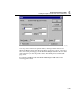
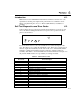

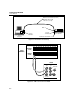
Table Of Contents
- 2640A/2645A NetDAQ Users Manual
- 1. Overview
- 2. Preparing for Operation
- Introduction
- Instrument Preparation
- Unpacking and Inspecting the Instrument
- Positioning and Rack Mounting
- Connecting to a Power Source and Grounding
- Universal Input Module Connections
- Digital I/O Connections
- Alarm/Trigger I/O Connections
- External Trigger Wiring for a Group Instrument
- Controls and Indicators
- Front Panel Operating Procedures
- Power-On Options
- Displaying a Monitor Channel
- Displaying the Digital I/O Status
- Displaying the Totalizer Status
- Reviewing and Setting the Base Channel Number
- Reviewing and Setting the Line Frequency
- Reviewing and Setting the Network Type
- Reviewing and Setting the General Network Socket Port
- Reviewing and Setting the General Network IP Address
- Reviewing and Setting the Subnet Mask and Default Gateway
- Viewing the Instrument Ethernet Address
- Host Computer and Network Preparation
- Testing and Troubleshooting
- 3. Configuring NetDAQ Logger for Windows
- Introduction
- Configuring Network Communications
- Configuring the Current Setup
- Setup Files
- Configuring an Instrument
- Configuring Channels
- Configuring Mx+B Scaling From a File
- Entering an Instrument's Description
- Copying a Channels Configuration
- Default Configuration Settings
- Using Configuration Lockout
- Saving an Instrument's Configuration as a Text File
- Configuring the netdaq.ini File
- 4. Operating NetDAQ Logger for
- 5. Using Trend Link for Fluke
- Introduction
- Getting the Right Look for Your Trend Link Chart
- 6. Maintenance
- Introduction
- Self-Test Diagnostics and Error Codes
- Cleaning
- Fuse Replacement
- Performance Test
- Configuring the Performance Test Setup
- Initializing the Performance Test Setup
- Accuracy Performance Tests
- Volts DC Accuracy Test (2640A)
- Volts DC Accuracy Test (2645A)
- Volts AC Accuracy Test
- Frequency Accuracy Test
- Analog Channel Integrity Test
- Computed Channel Integrity Test
- Thermocouple Temperature Accuracy Test
- Open Thermocouple Response Test
- 2-Wire Resistance Accuracy Test (2640A)
- 2-Wire Resistance Accuracy Test (2645A)
- 4-Wire Resistance Accuracy Test (2640A)
- 4-Wire Resistance Accuracy Test (2645A)
- RTD Temperature Accuracy Test (Resistance) (2640A)
- RTD Temperature Accuracy Test (Resistance) (2645A)
- RTD Temperature Accuracy Test (DIN/IEC 751 RTD)
- Digital Input/Output Tests
- Totalizer Tests
- Master Alarm Output Test
- Trigger Input Test
- Trigger Output Test
- Calibration
- Variations in the Display
- Service
- Replacement Parts
- Appendices
- A. Specifications
- Introduction
- 2640A/2645A Combined Specifications
- 2640A Specifications
- 2640A DC Voltage Measurement Specifications
- 2640A AC Voltage Measurement Specifications
- 2640A 4-Wire Resistance Measurement Specifications
- 2640A 2-Wire Resistance Measurement Specifications
- 2640A RTD's 4-Wire, per ITS-1990 Measurement Specifications
- 2640A RTD's 2-Wire per ITS-1990 Measurement Specifications
- 2640A Thermocouple per ITS-1990 Measurement Specifications
- 2640A Frequency Measurement Specifications
- 2645A Specifications
- 2645A DC Voltage Measurement Specifications
- 2645A AC Voltage Measurement Specifications
- 2645A 4-Wire Resistance Measurement Specifications
- 2645A 2-Wire Resistance Measurement Specifications
- 2645A 4-Wire RTD per ITS-1990 Measurement Specifications
- 2645A Thermocouple per ITS-1990 Measurement Specifications
- 2645A Frequency Measurement Specifications
- B. Noise, Shielding, and Crosstalk Considerations
- C. True-RMS Measurements
- D. RTD Linearization
- E. Computed Channel Equations
- F. Data File Format
- G. Dynamic Data Exchange (DDE)
- H. Ethernet Cabling
- I. Network Considerations
- J. Error Messages & Exception Conditions
- K. Fluke Service Centers
- A. Specifications
- Index
- Instrument Parameter Record (Isolated Network)
- Instrument Parameter Record (General Network)
- General Network Parameter Record
- Host Computer General Network Parameter Record

Maintenance
Introduction
6
6-3
Introduction 6-1.
Maintenance for the 2640A/2645A instruments is limited to self-test error code
explanations, cleaning, fuse replacement, performance test, calibration, and a
listing of replacement parts. A Service Manual (PN 942615) is available for
purchase.
Self-Test Diagnostics and Error Codes 6-2.
Self-test diagnostics are performed each time the instrument is powered up. Any
errors encountered during this initial 5-second period are reported on the front
panel, as shown below.
If you encounter an error code, refer to Table 6-1 for a brief description of the
error. For all errors, try cycling the instrument power. If the error persists and you
intend to repair the instrument yourself, refer to the Service Manual, PN 942615.
Otherwise, package the instrument securely (using the original container, if
available), and mail it to the nearest Fluke Service Center. Include a description of
the problem. Fluke assumes no responsibility for damage in transit.
Table 6-1. Self-Test Error Codes
Error Code Error Description
1 Boot ROM Checksum Error
2 Instrument ROM Checksum Error
3 Internal RAM Test Failed
4 Display Power-Up Test Failed
5 Display Not Responding
6 Calibration Constants Corrupted
7 A-D Not Responding
8 A-D Self-Test Failed
9 A-D Zero Offset Test Failed
10 A-D Reference Balance Test Failed
11 A-D Overload Detection Test Failed
12 A-D Open Thermocouple Detection Test Failed
13 Communication Parameters (e.g., baud, IP address) Corrupted
14 Ethernet Address Corrupted
15 Internal RAM Constants Corrupted
16 Ethernet Chip Test Failed
17 Uncalibrated or Calibration Incomplete