
NetDAQ Users Manual
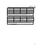
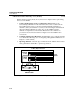
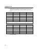
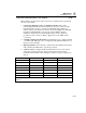
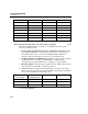
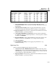
Table Of Contents
- 2640A/2645A NetDAQ Users Manual
- 1. Overview
- 2. Preparing for Operation
- Introduction
- Instrument Preparation
- Unpacking and Inspecting the Instrument
- Positioning and Rack Mounting
- Connecting to a Power Source and Grounding
- Universal Input Module Connections
- Digital I/O Connections
- Alarm/Trigger I/O Connections
- External Trigger Wiring for a Group Instrument
- Controls and Indicators
- Front Panel Operating Procedures
- Power-On Options
- Displaying a Monitor Channel
- Displaying the Digital I/O Status
- Displaying the Totalizer Status
- Reviewing and Setting the Base Channel Number
- Reviewing and Setting the Line Frequency
- Reviewing and Setting the Network Type
- Reviewing and Setting the General Network Socket Port
- Reviewing and Setting the General Network IP Address
- Reviewing and Setting the Subnet Mask and Default Gateway
- Viewing the Instrument Ethernet Address
- Host Computer and Network Preparation
- Testing and Troubleshooting
- 3. Configuring NetDAQ Logger for Windows
- Introduction
- Configuring Network Communications
- Configuring the Current Setup
- Setup Files
- Configuring an Instrument
- Configuring Channels
- Configuring Mx+B Scaling From a File
- Entering an Instrument's Description
- Copying a Channels Configuration
- Default Configuration Settings
- Using Configuration Lockout
- Saving an Instrument's Configuration as a Text File
- Configuring the netdaq.ini File
- 4. Operating NetDAQ Logger for
- 5. Using Trend Link for Fluke
- Introduction
- Getting the Right Look for Your Trend Link Chart
- 6. Maintenance
- Introduction
- Self-Test Diagnostics and Error Codes
- Cleaning
- Fuse Replacement
- Performance Test
- Configuring the Performance Test Setup
- Initializing the Performance Test Setup
- Accuracy Performance Tests
- Volts DC Accuracy Test (2640A)
- Volts DC Accuracy Test (2645A)
- Volts AC Accuracy Test
- Frequency Accuracy Test
- Analog Channel Integrity Test
- Computed Channel Integrity Test
- Thermocouple Temperature Accuracy Test
- Open Thermocouple Response Test
- 2-Wire Resistance Accuracy Test (2640A)
- 2-Wire Resistance Accuracy Test (2645A)
- 4-Wire Resistance Accuracy Test (2640A)
- 4-Wire Resistance Accuracy Test (2645A)
- RTD Temperature Accuracy Test (Resistance) (2640A)
- RTD Temperature Accuracy Test (Resistance) (2645A)
- RTD Temperature Accuracy Test (DIN/IEC 751 RTD)
- Digital Input/Output Tests
- Totalizer Tests
- Master Alarm Output Test
- Trigger Input Test
- Trigger Output Test
- Calibration
- Variations in the Display
- Service
- Replacement Parts
- Appendices
- A. Specifications
- Introduction
- 2640A/2645A Combined Specifications
- 2640A Specifications
- 2640A DC Voltage Measurement Specifications
- 2640A AC Voltage Measurement Specifications
- 2640A 4-Wire Resistance Measurement Specifications
- 2640A 2-Wire Resistance Measurement Specifications
- 2640A RTD's 4-Wire, per ITS-1990 Measurement Specifications
- 2640A RTD's 2-Wire per ITS-1990 Measurement Specifications
- 2640A Thermocouple per ITS-1990 Measurement Specifications
- 2640A Frequency Measurement Specifications
- 2645A Specifications
- 2645A DC Voltage Measurement Specifications
- 2645A AC Voltage Measurement Specifications
- 2645A 4-Wire Resistance Measurement Specifications
- 2645A 2-Wire Resistance Measurement Specifications
- 2645A 4-Wire RTD per ITS-1990 Measurement Specifications
- 2645A Thermocouple per ITS-1990 Measurement Specifications
- 2645A Frequency Measurement Specifications
- B. Noise, Shielding, and Crosstalk Considerations
- C. True-RMS Measurements
- D. RTD Linearization
- E. Computed Channel Equations
- F. Data File Format
- G. Dynamic Data Exchange (DDE)
- H. Ethernet Cabling
- I. Network Considerations
- J. Error Messages & Exception Conditions
- K. Fluke Service Centers
- A. Specifications
- Index
- Instrument Parameter Record (Isolated Network)
- Instrument Parameter Record (General Network)
- General Network Parameter Record
- Host Computer General Network Parameter Record
Maintenance
Performance Test
6
6-19
Resistance Range* Decade Resistor Minimum Reading Maximum Reading
30 kΩ
Short Circuit (Zero)
700Ω 1 kΩ
30 kΩ 29 kΩ 29.681 kΩ 30.019 kΩ
300 kΩ 290 kΩ 289.07 kΩ 292.63 kΩ
3 MΩ 2.9 MΩ 2.8607 MΩ 2.9410 MΩ
* The resistance accuracy in this table makes allowance for up to 0.1 Ohm of lead wire
resistance plus 0.01% decade resistance tolerance. You must add any additional lead wire
resistance present in your setup to the resistance values given in this table.
Resistance Range* 5700A Minimum Reading Maximum Reading
30 kΩ
Short Circuit (Zero)
700Ω 1 kΩ
30 kΩ 19 kΩ 19.686 kΩ 20.014 kΩ
300 kΩ 190 kΩ 189.60 kΩ 192.10 kΩ
3 MΩ 1.9 MΩ 1.8740 MΩ 1.9277 MΩ
* The resistance accuracy in this table makes allowance for up to 0.1 Ohm of lead wire
resistance. You must add any additional lead wire resistance present in your setup to the
resistance values given in this table.
5. Close Spy Window.