
NetDAQ Users Manual

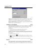
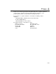

Table Of Contents
- 2640A/2645A NetDAQ Users Manual
- 1. Overview
- 2. Preparing for Operation
- Introduction
- Instrument Preparation
- Unpacking and Inspecting the Instrument
- Positioning and Rack Mounting
- Connecting to a Power Source and Grounding
- Universal Input Module Connections
- Digital I/O Connections
- Alarm/Trigger I/O Connections
- External Trigger Wiring for a Group Instrument
- Controls and Indicators
- Front Panel Operating Procedures
- Power-On Options
- Displaying a Monitor Channel
- Displaying the Digital I/O Status
- Displaying the Totalizer Status
- Reviewing and Setting the Base Channel Number
- Reviewing and Setting the Line Frequency
- Reviewing and Setting the Network Type
- Reviewing and Setting the General Network Socket Port
- Reviewing and Setting the General Network IP Address
- Reviewing and Setting the Subnet Mask and Default Gateway
- Viewing the Instrument Ethernet Address
- Host Computer and Network Preparation
- Testing and Troubleshooting
- 3. Configuring NetDAQ Logger for Windows
- Introduction
- Configuring Network Communications
- Configuring the Current Setup
- Setup Files
- Configuring an Instrument
- Configuring Channels
- Configuring Mx+B Scaling From a File
- Entering an Instrument's Description
- Copying a Channels Configuration
- Default Configuration Settings
- Using Configuration Lockout
- Saving an Instrument's Configuration as a Text File
- Configuring the netdaq.ini File
- 4. Operating NetDAQ Logger for
- 5. Using Trend Link for Fluke
- Introduction
- Getting the Right Look for Your Trend Link Chart
- 6. Maintenance
- Introduction
- Self-Test Diagnostics and Error Codes
- Cleaning
- Fuse Replacement
- Performance Test
- Configuring the Performance Test Setup
- Initializing the Performance Test Setup
- Accuracy Performance Tests
- Volts DC Accuracy Test (2640A)
- Volts DC Accuracy Test (2645A)
- Volts AC Accuracy Test
- Frequency Accuracy Test
- Analog Channel Integrity Test
- Computed Channel Integrity Test
- Thermocouple Temperature Accuracy Test
- Open Thermocouple Response Test
- 2-Wire Resistance Accuracy Test (2640A)
- 2-Wire Resistance Accuracy Test (2645A)
- 4-Wire Resistance Accuracy Test (2640A)
- 4-Wire Resistance Accuracy Test (2645A)
- RTD Temperature Accuracy Test (Resistance) (2640A)
- RTD Temperature Accuracy Test (Resistance) (2645A)
- RTD Temperature Accuracy Test (DIN/IEC 751 RTD)
- Digital Input/Output Tests
- Totalizer Tests
- Master Alarm Output Test
- Trigger Input Test
- Trigger Output Test
- Calibration
- Variations in the Display
- Service
- Replacement Parts
- Appendices
- A. Specifications
- Introduction
- 2640A/2645A Combined Specifications
- 2640A Specifications
- 2640A DC Voltage Measurement Specifications
- 2640A AC Voltage Measurement Specifications
- 2640A 4-Wire Resistance Measurement Specifications
- 2640A 2-Wire Resistance Measurement Specifications
- 2640A RTD's 4-Wire, per ITS-1990 Measurement Specifications
- 2640A RTD's 2-Wire per ITS-1990 Measurement Specifications
- 2640A Thermocouple per ITS-1990 Measurement Specifications
- 2640A Frequency Measurement Specifications
- 2645A Specifications
- 2645A DC Voltage Measurement Specifications
- 2645A AC Voltage Measurement Specifications
- 2645A 4-Wire Resistance Measurement Specifications
- 2645A 2-Wire Resistance Measurement Specifications
- 2645A 4-Wire RTD per ITS-1990 Measurement Specifications
- 2645A Thermocouple per ITS-1990 Measurement Specifications
- 2645A Frequency Measurement Specifications
- B. Noise, Shielding, and Crosstalk Considerations
- C. True-RMS Measurements
- D. RTD Linearization
- E. Computed Channel Equations
- F. Data File Format
- G. Dynamic Data Exchange (DDE)
- H. Ethernet Cabling
- I. Network Considerations
- J. Error Messages & Exception Conditions
- K. Fluke Service Centers
- A. Specifications
- Index
- Instrument Parameter Record (Isolated Network)
- Instrument Parameter Record (General Network)
- General Network Parameter Record
- Host Computer General Network Parameter Record
2640A/2645A NetDAQ
Users Manual
6-36
Fluke offers a 1-year warranty for the 264XA-801 (Ethernet plug-in card) and
264XA-802 (Ethernet Parallel-to-LAN adapter), and 264XA-803 (PCMCIA
Adapter) options. Defective units may be returned to either Fluke or to the option
manufacturer for repair or replacement. The original equipment manufacturer may
offer warranties beyond the warranty supplied by Fluke.
Replacement Parts 6-39.
Replacement parts are listed in Table 6-3. To order replacement parts in the USA,
call 1-800-526-4731. To order parts from outside the USA, contact the nearest
Fluke Service Center. (See Appendix K, “Fluke Service Centers.”). Other
instrument models, options and accessories are listed in Table 1-1.
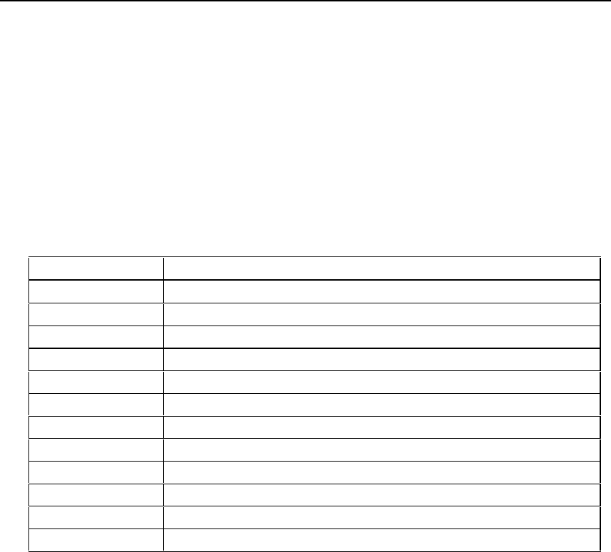
Table 6-3. Replacement Parts
Part Number Description
343723 Power Cable
851712 RS-232 Cable (for calibration) 9-pin socket to 25-pin socket
875877 ALARM/TRIGGER I/O Connector
875880 DIGITAL I/O Connector
926126 Replacement Fuse 15/100A, 250V, Time Delay (lot of 5 pieces)
926134 Replacement Fuse 15/100A, 250V, Time Delay (lot of 25 pieces)
942615 NetDAQ Service Manual
942813 BNC "Y" Connector
942834 BNC 50-Ohm Termination without Ground Wire for 10Base2
943600 4-meter 10Base2 Coaxial Ethernet Cable
944538 BNC 50-Ohm Termination with Ground Wire for 10Base2
944629 Replacement Fuse 15/100A, 250V, Time Delay