
NetDAQ Users Manual
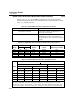
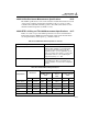
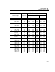
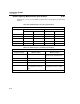
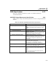
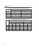
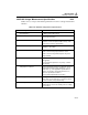
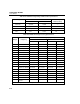
Table Of Contents
- 2640A/2645A NetDAQ Users Manual
- 1. Overview
- 2. Preparing for Operation
- Introduction
- Instrument Preparation
- Unpacking and Inspecting the Instrument
- Positioning and Rack Mounting
- Connecting to a Power Source and Grounding
- Universal Input Module Connections
- Digital I/O Connections
- Alarm/Trigger I/O Connections
- External Trigger Wiring for a Group Instrument
- Controls and Indicators
- Front Panel Operating Procedures
- Power-On Options
- Displaying a Monitor Channel
- Displaying the Digital I/O Status
- Displaying the Totalizer Status
- Reviewing and Setting the Base Channel Number
- Reviewing and Setting the Line Frequency
- Reviewing and Setting the Network Type
- Reviewing and Setting the General Network Socket Port
- Reviewing and Setting the General Network IP Address
- Reviewing and Setting the Subnet Mask and Default Gateway
- Viewing the Instrument Ethernet Address
- Host Computer and Network Preparation
- Testing and Troubleshooting
- 3. Configuring NetDAQ Logger for Windows
- Introduction
- Configuring Network Communications
- Configuring the Current Setup
- Setup Files
- Configuring an Instrument
- Configuring Channels
- Configuring Mx+B Scaling From a File
- Entering an Instrument's Description
- Copying a Channels Configuration
- Default Configuration Settings
- Using Configuration Lockout
- Saving an Instrument's Configuration as a Text File
- Configuring the netdaq.ini File
- 4. Operating NetDAQ Logger for
- 5. Using Trend Link for Fluke
- Introduction
- Getting the Right Look for Your Trend Link Chart
- 6. Maintenance
- Introduction
- Self-Test Diagnostics and Error Codes
- Cleaning
- Fuse Replacement
- Performance Test
- Configuring the Performance Test Setup
- Initializing the Performance Test Setup
- Accuracy Performance Tests
- Volts DC Accuracy Test (2640A)
- Volts DC Accuracy Test (2645A)
- Volts AC Accuracy Test
- Frequency Accuracy Test
- Analog Channel Integrity Test
- Computed Channel Integrity Test
- Thermocouple Temperature Accuracy Test
- Open Thermocouple Response Test
- 2-Wire Resistance Accuracy Test (2640A)
- 2-Wire Resistance Accuracy Test (2645A)
- 4-Wire Resistance Accuracy Test (2640A)
- 4-Wire Resistance Accuracy Test (2645A)
- RTD Temperature Accuracy Test (Resistance) (2640A)
- RTD Temperature Accuracy Test (Resistance) (2645A)
- RTD Temperature Accuracy Test (DIN/IEC 751 RTD)
- Digital Input/Output Tests
- Totalizer Tests
- Master Alarm Output Test
- Trigger Input Test
- Trigger Output Test
- Calibration
- Variations in the Display
- Service
- Replacement Parts
- Appendices
- A. Specifications
- Introduction
- 2640A/2645A Combined Specifications
- 2640A Specifications
- 2640A DC Voltage Measurement Specifications
- 2640A AC Voltage Measurement Specifications
- 2640A 4-Wire Resistance Measurement Specifications
- 2640A 2-Wire Resistance Measurement Specifications
- 2640A RTD's 4-Wire, per ITS-1990 Measurement Specifications
- 2640A RTD's 2-Wire per ITS-1990 Measurement Specifications
- 2640A Thermocouple per ITS-1990 Measurement Specifications
- 2640A Frequency Measurement Specifications
- 2645A Specifications
- 2645A DC Voltage Measurement Specifications
- 2645A AC Voltage Measurement Specifications
- 2645A 4-Wire Resistance Measurement Specifications
- 2645A 2-Wire Resistance Measurement Specifications
- 2645A 4-Wire RTD per ITS-1990 Measurement Specifications
- 2645A Thermocouple per ITS-1990 Measurement Specifications
- 2645A Frequency Measurement Specifications
- B. Noise, Shielding, and Crosstalk Considerations
- C. True-RMS Measurements
- D. RTD Linearization
- E. Computed Channel Equations
- F. Data File Format
- G. Dynamic Data Exchange (DDE)
- H. Ethernet Cabling
- I. Network Considerations
- J. Error Messages & Exception Conditions
- K. Fluke Service Centers
- A. Specifications
- Index
- Instrument Parameter Record (Isolated Network)
- Instrument Parameter Record (General Network)
- General Network Parameter Record
- Host Computer General Network Parameter Record

2640A/2645A NetDAQ
Users Manual
A-14
2640A RTD’s 2-Wire per ITS-1990 Measurement Specifications A-18.
The 2640A specifications for the 2-wire Resistance-Temperature Detector (RTD)
measurement function is based on the 4-wire RTD measurement specification
(above) except you add a nominal 5-Ohm (roughly 13ºC ) positive offset. This
value varies for each channel and temperature gradient (nominal +0.4%/ºC). Also
note that the resistance of the RTD wiring adds directly to the error. After 100
million operations of a measurement channel, the offset will increase at an
indeterminate rate.
2640A Thermocouple per ITS-1990 Measurement Specifications A-19.
Tables A-20 to A-21 provide 2640A specifications for the thermocouple
measurement function per ITS-1990.
Table A-20. 2640A Thermocouple General Specifications
Specification Characteristic
Input Impedance 100 MΩ minimum in parallel with 300 pF
Open Thermocouple Detect Operates by injecting a small ac signal into the
input after each measurement. A thermocouple
resistance greater than 1kΩ to 10kΩ is
detected as an open input.
Temperature Coefficient To calculate thermocouple accuracy for
temperatures between 28ºC and 60ºC, or -10ºC
and 18ºC, use a linear interpolation between
the two applicable points. e.g., if the applicable
spec at 28ºC is .6 and the spec at 60ºC is 1.1,
then the spec at 40ºC = (1.1-.6)*(40-28)/(60-
28)+.6= .5* (12/32) + .6 = .7875.
Accuracy at -20°C Multiply the -10°C to + 60°C accuracy
specification by 2. After 1 hour warm-up. For
accuracy between -10°C and -20°C, interpolate
linearly.