
NetDAQ Users Manual
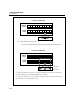
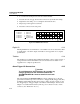
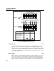
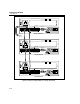
Table Of Contents
- 2640A/2645A NetDAQ Users Manual
- 1. Overview
- 2. Preparing for Operation
- Introduction
- Instrument Preparation
- Unpacking and Inspecting the Instrument
- Positioning and Rack Mounting
- Connecting to a Power Source and Grounding
- Universal Input Module Connections
- Digital I/O Connections
- Alarm/Trigger I/O Connections
- External Trigger Wiring for a Group Instrument
- Controls and Indicators
- Front Panel Operating Procedures
- Power-On Options
- Displaying a Monitor Channel
- Displaying the Digital I/O Status
- Displaying the Totalizer Status
- Reviewing and Setting the Base Channel Number
- Reviewing and Setting the Line Frequency
- Reviewing and Setting the Network Type
- Reviewing and Setting the General Network Socket Port
- Reviewing and Setting the General Network IP Address
- Reviewing and Setting the Subnet Mask and Default Gateway
- Viewing the Instrument Ethernet Address
- Host Computer and Network Preparation
- Testing and Troubleshooting
- 3. Configuring NetDAQ Logger for Windows
- Introduction
- Configuring Network Communications
- Configuring the Current Setup
- Setup Files
- Configuring an Instrument
- Configuring Channels
- Configuring Mx+B Scaling From a File
- Entering an Instrument's Description
- Copying a Channels Configuration
- Default Configuration Settings
- Using Configuration Lockout
- Saving an Instrument's Configuration as a Text File
- Configuring the netdaq.ini File
- 4. Operating NetDAQ Logger for
- 5. Using Trend Link for Fluke
- Introduction
- Getting the Right Look for Your Trend Link Chart
- 6. Maintenance
- Introduction
- Self-Test Diagnostics and Error Codes
- Cleaning
- Fuse Replacement
- Performance Test
- Configuring the Performance Test Setup
- Initializing the Performance Test Setup
- Accuracy Performance Tests
- Volts DC Accuracy Test (2640A)
- Volts DC Accuracy Test (2645A)
- Volts AC Accuracy Test
- Frequency Accuracy Test
- Analog Channel Integrity Test
- Computed Channel Integrity Test
- Thermocouple Temperature Accuracy Test
- Open Thermocouple Response Test
- 2-Wire Resistance Accuracy Test (2640A)
- 2-Wire Resistance Accuracy Test (2645A)
- 4-Wire Resistance Accuracy Test (2640A)
- 4-Wire Resistance Accuracy Test (2645A)
- RTD Temperature Accuracy Test (Resistance) (2640A)
- RTD Temperature Accuracy Test (Resistance) (2645A)
- RTD Temperature Accuracy Test (DIN/IEC 751 RTD)
- Digital Input/Output Tests
- Totalizer Tests
- Master Alarm Output Test
- Trigger Input Test
- Trigger Output Test
- Calibration
- Variations in the Display
- Service
- Replacement Parts
- Appendices
- A. Specifications
- Introduction
- 2640A/2645A Combined Specifications
- 2640A Specifications
- 2640A DC Voltage Measurement Specifications
- 2640A AC Voltage Measurement Specifications
- 2640A 4-Wire Resistance Measurement Specifications
- 2640A 2-Wire Resistance Measurement Specifications
- 2640A RTD's 4-Wire, per ITS-1990 Measurement Specifications
- 2640A RTD's 2-Wire per ITS-1990 Measurement Specifications
- 2640A Thermocouple per ITS-1990 Measurement Specifications
- 2640A Frequency Measurement Specifications
- 2645A Specifications
- 2645A DC Voltage Measurement Specifications
- 2645A AC Voltage Measurement Specifications
- 2645A 4-Wire Resistance Measurement Specifications
- 2645A 2-Wire Resistance Measurement Specifications
- 2645A 4-Wire RTD per ITS-1990 Measurement Specifications
- 2645A Thermocouple per ITS-1990 Measurement Specifications
- 2645A Frequency Measurement Specifications
- B. Noise, Shielding, and Crosstalk Considerations
- C. True-RMS Measurements
- D. RTD Linearization
- E. Computed Channel Equations
- F. Data File Format
- G. Dynamic Data Exchange (DDE)
- H. Ethernet Cabling
- I. Network Considerations
- J. Error Messages & Exception Conditions
- K. Fluke Service Centers
- A. Specifications
- Index
- Instrument Parameter Record (Isolated Network)
- Instrument Parameter Record (General Network)
- General Network Parameter Record
- Host Computer General Network Parameter Record
2640A/2645A NetDAQ
Users Manual
2-12
2. Loosen the wire clamp screw for the associated terminal.
3. Feed the wire into the gap between the connector body and the wire clamp.
4. Tighten the wire clamp; do not overtighten and crush the wire.
5. Repeat steps 2 through 4 for each wire.
6. Insert the connector in the rear panel.
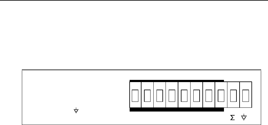
DIGITAL I/O
01234567
0
1
2
3
4
I/O Line 0
I/O Line 1
I/O Line 2
I/O Line 3
I/O Line 4
5
6
7
Σ
I/O Line 5
I/O Line 6
I/O Line 7
Totalizer Input
Signal Ground
Figure 2-5. DIGITAL I/O Connector
Digital I/O 2-13.
The Digital I/O lines use terminals 0 to 7 and GND. You can use these lines either
as signal inputs or as alarm outputs. See Table A-3 in Appendix A for complete
specifications.
Totalizer 2-14.
The Totalizer uses terminals Σ and GND. The Totalizer counts contact closures or
voltage transitions with a maximum count of 4,294,967,295. See Table A-7 in
Appendix A for complete specifications.
Alarm/Trigger I/O Connections 2-15.
PCaution
To avoid damage to the instrument, do not apply any
voltages greater than 30V maximum between the
ALARM/TRIGGER I/O connector terminals and earth
ground.
The eight-terminal ALARM/TRIGGER I/O connector (Figure 2-6) on the rear
panel of the instrument provides connections to Trigger In (TI), Trigger Out (TO),
and Master Alarm (MA) I/O lines along with a common ground connection. (See
the "Trigger Input," "Trigger Output," and "Master Alarm Output" discussions in
Chapter 1 for additional information.) The dc power connection is also on this
connector. (See "DC Power" above.).