® Fluke 123/124 Industrial ScopeMeter Users Manual GB Sep 2002 © 2002 Fluke Corporation. All rights reserved. All product names are trademarks of their respective companies.
LIMITED WARRANTY & LIMITATION OF LIABILITY Each Fluke product is warranted to be free from defects in material and workmanship under normal use and service. The warranty period is three years for the Test Tool and one year for its accessories. The warranty period begins on the date of shipment. Parts, product repairs and services are warranted for 90 days.
SERVICE CENTERS To locate an authorized service center, visit us on the World Wide Web: http://www.fluke.com or call Fluke using any of the phone numbers listed below: +1-888-993-5853 in U.S.A.
Table of Contents Chapter Title Page Declaration of Conformity ....................................................................................................... 1 Unpacking the Test Tool Kit ........................................................................................... 2 Safely Using the Test Tool ............................................................................................. 4 1 Using The Test Tool........................................................................
Fluke 123/124 Users Manual Freezing the Screen....................................................................................................... Holding a Stable Reading .............................................................................................. Making Relative Measurements..................................................................................... Selecting Auto/Manual Ranges......................................................................................
Contents (continued) Goal of this Chapter ....................................................................................................... Using the Tilt Stand........................................................................................................ Resetting the Test Tool .................................................................................................. Changing the Information Language..............................................................................
Declaration of Conformity Declaration of Conformity for Fluke 123/124 ScopeMeter® test tool Manufacturer Fluke Industrial B.V. Lelyweg 1 7602 EA Almelo The Netherlands Statement of Conformity Based on test results using appropriate standards, the product is in conformity with Electromagnetic Compatibility Directive 89/336/EEC Low Voltage Directive 73/23/EEC Sample tests Standards used: EN 61010.
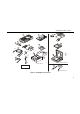
Fluke 123/124 Users Manual Unpacking the Test Tool Kit The following items are included in your test tool kit. (see Figure 1.): # 2 Description Note When new, the rechargeable battery pack is not fully charged. See Chapter 2.
Unpacking the Test Tool Kit 1 9 12 2 3 (2x) 13 10 4 6 (2x) 14 (3x) 7 5 8 11 * Fluke 123-S/124-S Fluke 123/124 * Fluke 123/124 : 1x Fluke 123-S/124-S : 2x 15 Fluke 124/124-S Figure 1.
Fluke 123/124 Users Manual Safely Using the Test Tool See explanation in manual Equal potential inputs Disposal information Earth Safety Precautions Recycling information Conformité Européenne Specific warning and caution statements, where they apply, will be found throughout the manual. Double Insulation UL listed Attention Carefully read the following safety information before using the test tool. A Caution identifies conditions and actions that may damage the test tool.
Safely Using the Test Tool Warning To avoid electrical shock or fire: • Use only the power supply, Model PM8907 (Battery Charger / Power Adapter). • Before use check that the selected/indicated voltage range on the PM8907 matches the local line power voltage and frequency. • For the PM8907/808 universal Battery Charger/Power Adapter use only line cords that comply with the local safety regulations.
Fluke 123/124 Users Manual • Do not insert metal objects into connectors. • Always use the Test Tool only in the manner specified. Max. Input Voltages Input A and B directly ............................... 600 V CAT III Input A and B via BB120 .......................... 300 V CAT III Input A and B via STL120 ........................ 600 V CAT III Max. Floating Voltage From any terminal to ground .................... 600 V CAT III Voltage ratings are given as “working voltage”.
Chapter 1 Using The Test Tool Goal of this Chapter This Chapter provides a step-by-step introduction to the test tool. The introduction does not cover all of the capabilities of the test tool but gives basic examples to show how to use the menus perform basic operations. Powering the Test Tool Follow the procedure (step 1 to 3) in Figure 1-1 to power the test tool from a standard ac outlet. See Chapter 2 for battery power instructions. Turn the test tool on.
Fluke 123/124 Users Manual Resetting the Test Tool If you want to restore the test tool settings as delivered from the factory, do the following: Turn the test tool off. Press and hold. Press and release. The test tool turns on, and you should hear a double beep, indicating the Reset was successful. Release. Now look at the display; you will see a screen that looks like Figure 1-2.
Using The Test Tool Changing Backlight Changing Backlight In Fluke 124, do the following: After power-up, the screen has a high bright display. To save battery power, the screen has an economic brightness display when operated on the battery pack (no power adapter connected). Press to get access to the display functions. Select LIGHT Dim or brighten the backlight. Note 1 Using dimmed display lengthens maximum battery power operation time.
Fluke 123/124 Users Manual Reading the Screen The screen is divided into three areas: Reading area, Waveform area, and Menu area. Refer to Figure 1-3 during the following. Reading area (A): Displays the numeric readings. Because only input A is on, you will see the input A readings only. Waveform area (B): Displays the input A waveform. The bottom line displays the ranges/div and the power indicator (line or battery). Because only input A is on, you will see the input A waveform only.
Using The Test Tool Making Selections in a Menu Making Selections in a Menu 1 Figure 1-4 shows the basic navigation of the test tool. Subsequently follow steps to to open a menu and to choose an item. Press the SCOPE MENU key to open the Scope menu. Note Pressing the SCOPE MENU key a second time closes this menu and resumes normal measurement. This toggling enables you to check the menu without destroying your settings. Use the blue arrow keys to highlight the item.
Fluke 123/124 Users Manual Looking at the Measurement Connections Look at the top of the test tool. The test tool provides two 4-mm safety shielded banana jack inputs (red input A and gray input B) and a safety 4-mm banana jack input (COM). (See Figure 1-5.) Figure 1-5. Measurement Connections Input A You can always use the red input A for all single input measurements possible with the test tool.
Using The Test Tool Displaying an Unknown Signal with Connect-and View™ 1 Displaying an Unknown Signal with Connect-and View™ The Connect-and-View™ function enables hands-off operation to display complex unknown signals. This function optimizes the position, range, time base, and triggering and assures a stable display on nearly all waveforms. If the signal changes, the setup will track these changes.
Fluke 123/124 Users Manual Making Measurements The reading area displays the numeric readings of the chosen measurements on the waveform that is applied to the input jack. • First connect the red shielded test lead from input A, and the gray shielded test lead from input B to the signals to be measured. Connect the short ground leads to the same ground potential. (See Figure 1-7.
Using The Test Tool Making Measurements To choose also a Peak-to-Peak measurement for Input B, do the following: Open the INPUT B menu. Highlight PEAK-PEAK. Accept the pk-pk measurement. 1 Now, you will see a screen like Figure 1-8. Highlight ON. Turn Input B on. Observe that the highlight jumps to the present main measurement. Highlight PEAK... Open the PEAK submenu. Figure 1-8.
Fluke 123/124 Users Manual Freezing the Screen Holding a Stable Reading You can freeze the screen (all readings and waveforms) at any time. The Touch Hold function captures and freezes the next stable measurement result. A beep indicates that a stable measurement has been made. Freeze the screen. HOLD appears at the bottom of the reading area. Resume your measurement. ® Use the following procedure for the Touch Hold function: Open the INPUT A menu.
Using The Test Tool Making Relative Measurements 1 Making Relative Measurements Zero Reference displays the present measurement result with respect to the defined value. This feature is useful when you need to monitor the measured value in relation to a known good value. Open the INPUT A menu. Open the METER A OPTIONS submenu. Figure 1-9. Making a Relative Measurement (2x) Jump to ZERO REF. Highlight ON. Activate the relative measurement.
Fluke 123/124 Users Manual Selecting Auto/Manual Ranges Press to automatically adjust the position, range, time base, and triggering. This assures a stable display on nearly all waveforms. The bottom line shows the range, the time base for both inputs, and the trigger information. a second time to select the manual range. Press MANUAL appears at the bottom of the reading area.
Using The Test Tool Changing the Graphic Representation on the Screen 1 Positioning the Waveform on the Screen Considerable flexibility is offered in moving the waveform(s) around the screen. Press until you have left any open menu. Observe that the following main menu appears on bottom of the screen. Choose A MOVE. Position the waveform of INPUT A on the screen. Waveform positioning is demonstrated in Figure 1-10. Observe that the trigger identifier ( ) moves horizontally on the screen.
Fluke 123/124 Users Manual Smoothing the Waveform To smooth the waveform, do the following: Open the SCOPE INPUTS menu. Open the SCOPE OPTIONS submenu. Jump to WAVEFORM MODE. Highlight SMOOTH. Accept waveform smooth. You can use waveform smooth to suppress noise without loss of bandwidth. Waveform samples with and without smoothing are shown in Figure 1-11. 20 Figure 1-11.
Using The Test Tool Changing the Graphic Representation on the Screen 1 Displaying the Envelope of a Waveform The test tool records the envelope (minimum and maximum) of the live waveforms A and B. Repeat the first three actions of ‘Smoothing the Waveform’, and then do the following: Highlight ENVELOPE. Start monitoring the envelope of the waveform. The screen shows the resultant envelope in a gray waveform. See Figure 1-12.
Fluke 123/124 Users Manual TrendPlotting a Waveform The TrendPlot™ function plots the digital readings as a function of time. Date and time stamp shows the time of the most recent change in a MIN or MAX reading. Starting a TrendPlot™ function Open the INPUT A menu. Start TRENDPLOT. The test tool records the minimum (MIN) reading as the main (upper displayed) measurement of input A. The date and time stamp appear below the MIN reading. (See Figure 1-13.
Using The Test Tool Acquiring the Waveform Changing the TrendPlot Reading Acquiring the Waveform To toggle the TrendPlot reading between MIN (minimum), MAX (maximum), and AVERAGE, do the following: Making a Single Acquisition Change MIN into MAX reading. Change MAX into AVG reading. Note that the date and time stamp now updates continuously to indicate the most recent change in a reading. Turning Off the TrendPlot Display 1 To catch single events, you can perform a single shot.
Fluke 123/124 Users Manual Wait appears on bottom of the screen to indicate that the test tool is waiting for a trigger. Run appears on bottom of the screen when the single acquisition is triggered. Hold appears on bottom of the screen when the single acquisition has been completed. The test tool will now have a screen like Figure 1-14. To perform a next single acquisition, do the following: Wait for another single acquisition trigger. Figure 1-14.
Using The Test Tool Acquiring the Waveform 1 Recording Slow Signals over a Long Period of Time The roll mode function supplies a visual log of waveform activity and is especially useful when you measure lower frequency waveforms. Open the SCOPE INPUTS menu. Open the SCOPE OPTIONS submenu. Highlight ROLL MODE. (2x) Figure 1-15. Recording Waveforms over Longer Period of Time Start Recording. The waveform moves accross the screen from right to left like a normal chart recorder.
Fluke 123/124 Users Manual Selecting AC-Coupling Use AC-coupling when you wish to observe a small AC signal that rides on a DC signal. Reversing the Polarity of the Displayed Waveform To invert the input A waveform, do the following: Open the SCOPE INPUTS menu. Open the SCOPE INPUTS menu. Highlight AC. Select NORMAL (of INPUT A). Accept AC-coupling for INPUT A. Highlight INVERT. (4x) (3x) Accept inverted waveform display.
Using The Test Tool Triggering on a Waveform 1 Triggering on a Waveform Triggering tells the test tool when to begin displaying the waveform. You can select which input signal should be used, on which edge this should occur, and you can define the condition for a new update of the waveform. Finally you can tell the test tool to trigger on video signals. Adjust the Trigger Level continuously. Observe the trigger icon on the second time division line indicates the trigger level.
Fluke 123/124 Users Manual Selecting the Trigger Parameters To trigger on the input A waveform, with automatic screen update, and to configure the auto range triggering for waveforms from 1 Hz, do the following: Open the SCOPE INPUTS menu. Open the TRIGGER submenu. Accept all trigger selections and return to normal measurement. Note Setting the automatic triggering to >1Hz will slow down the auto range. TRIG:A appears in gray text on bottom of the screen when no trigger is found.
Using The Test Tool Triggering on a Waveform Isolated Triggering Use the optically isolated trigger probe (ITP120, optional) to trigger on an external source, and to isolate the test tool from a trigger waveform. See Figure 1-17. To choose the isolated trigger probe, select ‘EXT’ in point of the previous example. Trigger level is fixed and is TTL compatible. Figure 1-17. Isolated Triggering 1 Triggering on Video Signals • Apply an interlaced video signal to the red input A.
Fluke 123/124 Users Manual Highlight POSITIVE. Accept the video trigger selections . Trigger level and slope are now fixed. (See Figure 1-18.) Positive video is indicated as a “+” icon on bottom of the screen. Figure 1-18.
Using The Test Tool Triggering on a Waveform Triggering on a Specific Video Line Pressing To view a specific video line in more detail you can select the line number. To measure on a selected video line, continue from point of the previous example as follows: To choose line 135, do the following: Highlight SELECT Select SELECT Highlight POSITIVE. Accept the video trigger selections . 1 selects the line number function. Enable video line selection. Select number 135.
Fluke 123/124 Users Manual Saving and Recalling a Setup and a Screen You can save Screens and Setups to memory, and recall them again for later use. Fluke 123 has 10 memories while Fluke 124 has 20 memories. In each memory you can save a screen and the related settings. Saving Screens with Belonging Setups To save a screen and setups in e.g. memory location 7, do the following: Note that free memory locations are indicated by an open square ( ) in front of the memory number.
Using The Test Tool Saving and Recalling a Setup and a Screen Recalling Screens and Setups Highlight memory 7. View the saved screen and belonging settings. 1 To recall a screen and setups, do the following: Open the SAVE/PRINT menu. Highlight RECALL ... Open the RECALL ... submenu. Observe that the recalled waveform is displayed and that HOLD appears on the screen. From this point you can use cursors for analysis or you can print the recalled screen.
Fluke 123/124 Users Manual Deleting Screens and Associated Setups To delete all or just 1 screen + setups, do the following: Open the SAVE/PRINT menu. If you want to clear all memory locations, press F3 DELETE ALL. If you want to clear just 1 memory location (e.g. memory 7), do the following: Highlight DELETE ... Open the DELETE ... submenu. Filled memory locations are indicated with a closed square. 34 Highlight memory 7.
Using The Test Tool Making Cursor Measurements Making Cursor Measurements Fluke 124 has cursors. Cursors allow you to make precise digital measurements on waveforms. This can be done on live waveforms and on saved waveforms. 1 Note Even when the key labels are not displayed at the bottom of the screen, you can still use the arrow keys. Using Horizontal Cursors on a Waveform To use the cursors for a voltage measurement, do the following: From Scope mode, display the Cursor Key functions.
Fluke 123/124 Users Manual The readout shows the voltage difference between the two cursors and the voltages at the cursors in relation to the zero icon (-). See Figure 1-19). Use horizontal cursors to measure the amplitude, high and low value, or overshoot of a waveform. ⑥ Highlight the right cursor. ⑦ Move the right cursor to the desired position on the waveform.
Using The Test Tool Making Cursor Measurements The readout shows the time difference ‘t’ between the cursors and the voltage difference between the two markers (See Figure 1-20). The signal frequency is displayed behind 1/t if exactly 1 signal period is between the cursors. Highlight the other cursor. ⑥ Move the lower cursor to 0% of the trace height. A marker is shown at 10%.
Fluke 123/124 Users Manual The reading now shows the risetime from 10%-90% of the trace amplitude and the voltage at the cursors in relation to the zero icon (-). See Figure 1-21. ⑦ Turn off the cursors. Using the 10:1 Probe for High Frequency Measurements. Fluke 124 is supplied with a model VP40 10:1 Probe. Use of this Probe is recommended when you measure high frequency signals in circuits with a high impedance.
Using The Test Tool Using a Printer ⑥ Press ENTER to confirm the selection. Observe that the 10 times attenuation of the Probe is compensated in the voltage readout. Using a Printer To print a (graphic) hard copy of the present screen, you need to use one of the following: The Optically Isolated RS-232 Adapter/Cable (PM9080) to connect a serial printer to the OPTICAL PORT of the test tool. See Figure 1-22.
Fluke 123/124 Users Manual This example covers how to set up the test tool to print on a HP Deskjet printer with a baudrate of 9600 baud: Open the SAVE&PRINT menu. Observe that the screen is freezed. Open the PRINTER SETUP submenu. Highlight DESKJET. Select DESKJET. Highlight 9600. Accept the print selections. Figure 1-22. Connecting a Serial Printer Figure 1-23.
Using The Test Tool Using FlukeView® Software Now you are ready to print. Using FlukeView® Software To print a live screen, do the following: Open the SAVE&PRINT menu. To connect the test tool to a computer for using the ® FlukeView software for Windows (SW90W), do the following: Start printing. To print a recalled screen, do the following: Start printing. A message that indicates that the test tool is printing appears on bottom of the screen.
Fluke 123/124 Users Manual Figure 1-24.
Chapter 2 Maintaining the Test Tool About this Chapter Cleaning the Test Tool This chapter covers basic maintenance procedures that can be performed by the user. For complete service, disassembly, repair, and calibration information, see the Service Manual. You will find the part number of the Service Manual in the section ‘Parts and Accessories’ in this manual. Clean the test tool with a damp cloth and a mild soap to avoid abrasion of text on the test tool. Do not use abrasives, solvents, or alcohol.
Fluke 123/124 Users Manual Charging the Rechargeable Battery Pack At delivery, the batteries may be empty and must be charged (test tool is off) to fill them completely. Charging time is 5 hours for Fluke 123 (Ni-Cd battery) and 7 hours for Fluke 124 (Ni-MH battery). When fully charged, the batteries typically provide 4 hours of use in Fluke 123 and 6 hours in Fluke 124 at full brightness. Operating time is extended at normal brightness.
Maintaining the Test Tool Keeping Batteries in Optimal Condition Keeping Batteries in Optimal Condition Always operate the test tool on batteries until an -icon appears on the bottom line of the screen. This indicates that the battery level is low and that the batteries need to be recharged. Frequent charging of the batteries when they are not completely empty can reduce the operating time for the test tool. You can refresh the battery pack at any time.
Fluke 123/124 Users Manual Replacing and Disposing of the Rechargeable Battery Pack Warning To avoid electrical shock, remove the test leads and probes before replacing the battery pack. Note This instrument contains Ni-Cd or Ni-MH batteries. Do not dispose of this battery pack with other solid waste. Used batteries should be disposed of by a qualified recycler or hazardous materials handler. Contact your authorized FLUKE Service Center for recycling information.
Maintaining the Test Tool Using and Adjusting 10:1 Scope Probes Note Ensure that the battery pack is placed in the battery compartment as shown in Figure 2-2. For Fluke 123 use the Fluke BP120 Ni-Cd (standard) or BP130 Ni-MH (extended operating time) battery pack. For Fluke 124 it is recommended to use the Fluke BP130 Ni-MH battery pack . 8. • 2 Connect the 10:1 scope probe from the gray input B jack to the red input A jack.
Fluke 123/124 Users Manual Open the SCOPE INPUTS menu. Open the PROBES submenu. Highlight PROBE AC ADJUST. Open the PROBE AC ADJUST submenu. Highlight ADJUST 10:1 PROBE. A square wave appears on the screen. 48 Adjust the trimmer screw in the probe housing to give an optimum square wave. Return to normal mode.
Maintaining the Test Tool Calibrating the Test Tool Calibrating the Test Tool Parts and Accessories You can ask for the model identity (version and calibration data) at any time. To display the identity, do the following: Service Manual Open the USER OPTIONS menu. Open the VERSION&CALIBRATION submenu. 2 Ordering Number: 4822 872 05389 Standard Accessories The next tables list the user-replaceable parts for the various test tool models.
Fluke 123/124 Users Manual Standard Accessories (cont) Item Ordering Code Ni-Cd Battery Pack (installed in Fluke 123, 123/S) BP120 Ni-MH Battery Pack (installed in Fluke 124, 124/S) BP130 Power Adapter/Battery Charger, available models: Universal Europe 230V, 50Hz North America 120V, 60Hz United Kingdom 240V, 50Hz Japan 100V, 60Hz Australia 240V, 50Hz Universal 115V/230V * * UL listing applies to PM8907/808 with UL listed line plug adapter for North America.
Maintaining the Test Tool Parts and Accessories 2 Standard Accessories (cont) Item Ordering Code Test Lead for Grounding (Black) TL75 Set of two Hook Clips (Red and Gray) HC120 Set of three Alligator Clips (Red, Gray, and Black) AC120 One Banana-to-BNC Adapter (Black). Supplied with: Fluke 123, 124 BB120 (Set of two) Two Banana-to-BNC Adapters (Black).
Fluke 123/124 Users Manual Optional Accessories Item Ordering Code Software & Cable Carrying Case Kit (Supplied with Fluke 123/S, 124/S) SCC 120 Set contains the following parts: PM9080 Optically Isolated RS-232 Adapter/Cable Hard Carrying Case. Supplied with Fluke 123/S, 124/S ® ® FlukeView ScopeMeter Software for Windows ® C120 SW90W 10:1 Scope Probe VP40. Supplied with Fluke 124, 124/S VPS40 (Set of two) Optically Isolated RS-232 Adapter/Cable. PM9080 Hard Carrying Case.
Chapter 3 Tips and Troubleshooting Goal of this Chapter This Chapter gives you information and tips on how you can make the best use of the test tool. Using the Tilt Stand The test tool is equipped with a tilt stand, allowing viewing from an angle. You can also use the tilt stand to hang the test tool at a convenient viewing position. Simply tilt the stand and hang the test tool. Typical positions are shown in Figure 3-1. Figure 3-1.
Fluke 123/124 Users Manual Resetting the Test Tool Open the USER OPTIONS menu. Perform a Master Reset to make sure that your test tool is in the initial settings condition. Open the LANGUAGE SELECT submenu. Highlight ITALIANO. Accept ITALIANO (Italian) as language. Turn the test tool off. Press and hold. Press and release. The test tool turns on, and you should hear a double beep, indicating the Reset was successful. Release.
Tips and Troubleshooting Changing the Display Changing the Display Adjusting the Screen Contrast in Fluke 123 From the main menu, choose CONTRAST. Adjust the contrast of the screen. 3 Setting the Grid Display To choose a dotted grid, do the following: Open the USER OPTIONS menu. Highlight GRID TYPE. Open the GRID TYPE submenu. Choose DOTS. Accept the new grid display. Adjusting the Screen Contrast in Fluke 124 Switch from cursor control to display control.
Fluke 123/124 Users Manual Changing Date and Time Jump to DAY. The test tool has a date and time clock. To change the date to (e.g.) 20 June, 2002, do the following: Choose 20. Jump to FORMAT. Choose DD/MM/YY. Open USER OPTIONS menu. Accept the new date. You can change the time in a similar way by opening the TIME ADJUST submenu. (steps and .) Highlight DATE ADJUST. Open DATE ADJUST submenu. Choose 2002. Jump to MONTH. Choose 06.
Tips and Troubleshooting Saving Battery Life Saving Battery Life When operated on the battery pack (no Power Adapter connected), the test tool conserves power by shuting itself down. If you have not pressed a key for at least 30 minutes, the test tool turns itself off automatically. Open the submenu. Highlight AFTER 5 MIN. Accept the new power down time. 3 Note If the Power Adapter is connected, there is no automatic power shutdown.
Fluke 123/124 Users Manual Changing the Auto Set Options Highlight UNCHANGED. Normally, the Auto Set function captures waveforms from 15 Hz. Accept the new Auto Set configuration. To configure Auto Set for waveforms from 1 Hz with unchanged input coupling, do the following: Note Setting the Auto Set adjust to 1 Hz will slow down the Auto Set response. Open the User Options menu. Highlight AUTOSET ADJUST... Open the AUTOSET ADJUST submenu. Highlight SIGNALS > 1 Hz.
Tips and Troubleshooting Using Proper Grounding 3 Using Proper Grounding Incorrect grounding can cause various problems. This Section gives you guidelines for proper grounding. Use the short ground lead(s) when measuring DC or AC signals on input A and input B. (See Figure 3-2.) Warning To avoid electrical shock or fire, use only one COM (common) connection , or ensure that are at the same all connections to COM potential. Figure 3-2.
Fluke 123/124 Users Manual Solving Printing and Other Communication Errors RS-232 communication may cause problems. When experiencing communication problems, try the following remedies: Make sure that the interface cable is connected to the correct port on the printer or computer. If necessary use the 9 pin to 25 pin adapter or gender changer. Make sure that you have selected the correct printer type. (To select printer type, see Chapter 1.
Chapter 4 Specifications Introduction Performance Characteristics FLUKE guarantees the properties expressed in numerical values with the stated tolerance. Specified non-tolerance numerical values indicate those that could be nominally expected from the mean of a range of identical ScopeMeter test tools. Environmental Data The environmental data mentioned in this manual are based on the results of the manufacturer’s verification procedures.
Fluke 123/124 Users Manual Dual Input Oscilloscope Vertical Frequency Response DC Coupled: excluding probes and test leads (via BB120):................ Fluke 123: DC to 20 MHz (-3 dB) Fluke 124: DC to 40 MHz (-3 dB) with STL120 1:1 shielded test leads: ............................. DC to 12.5 MHz (-3 dB) DC to 20 MHz (-6 dB) with VP40 10:1 probe:....................................................
Specifications Dual Input Oscilloscope 4 Horizontal Trigger Scope Modes ...................................Normal, Single, Roll Screen Update .............................. Free Run, On Trigger Ranges Normal: equivalent sampling (Fluke 123) ..... 20 ns to 500 ns/div equivalent sampling (Fluke 124) ..... 10 ns to 500 ns/div real time sampling ................................... 1 µs to 5 s/div Single (real time) ..................................... 1 µs to 5 s/div Roll (real time).....................
Fluke 123/124 Users Manual Advanced Scope Functions Display Modes Normal........Captures up to 40 ns glitches and displays analog-like persistence waveform. Smooth.......Suppresses noise from a waveform. Envelope ....Records and displays the minimum and maximum of waveforms over time. Auto Set Continuous fully automatic adjustment of amplitude, time base, trigger levels, trigger gap, and hold-off. Manual override by user adjustment of amplitude, time base, or trigger level.
Specifications Dual Input Meter Dual Input Meter The accuracy of all measurements is within ± (% of reading + number of counts) from 18 °C to 28 °C. Add 0.1x (specific accuracy) for each °C below 18 °C or above 28 °C. For voltage measurements with 10:1 probe, add probe uncertainty +1%. More than one waveform period must be visible on the sceen. Input A and Input B DC Voltage (VDC) Ranges........................ 500 mV, 5V, 50V, 500V, 1250V Accuracy ..........................................±(0.
Fluke 123/124 Users Manual Accuracy: @1 Hz to 1 MHz ............................ ±(0.5% +2 counts) @1 to 10 MHz ............................... ±(1.0% +2 counts) @10 to 50 MHz (Fluke 123) .......... ±(2.5% +2 counts) @10 to 70 MHz (Fluke 124) .......... ±(2.5% +2 counts) (50 MHz in Autorange) Full Scale Reading ..................................10 000 counts Duty Cycle (DUTY) Range...........................................................2% to 98% Frequency Range in Continuous Autoset .....................
Specifications Dual Input Meter Input A Ohm (Ω Ω) Ranges ....... 500Ω, 5 kΩ, 50 kΩ, 500 kΩ, 5 MΩ, 30 MΩ Accuracy: .........................................±(0.6% +5 counts) Full Scale Reading: 500Ω to 5 MΩ ......................................... 5000 counts 30 MΩ..................................................... 3000 counts Measurement Current ......................... 0.5 mA to 50 nA decreases with increasing ranges Open Circuit Voltage ...............................................
Fluke 123/124 Users Manual Advanced Meter Functions Cursor readout (Fluke 124) Zero Set Set actual value to reference Sources: A, B Single Vertical Line: Average, Min and Max Readout Average, Min, Max and Time from Start of Readout (in ROLL mode; instrument in HOLD) Min, Max and Time from Start of Readout (in TRENDPLOT mode; instrument in HOLD) Dual Vertical Lines: Peak-Peak, Time Distance and Reciprocal Time Distance Readout Average, Min, Max and Time Distance Readout (in ROLL mode; instrument in HOLD)
Specifications Miscellaneous Miscellaneous Display Size ....................................72 x 72 mm (2.83 x 2.83 in) Resolution ............................................240 x 240 pixels Waveform Display: Vertical .............................................8 div of 20 pixels Horizontal ......................................9.6 div of 25 pixels Backlight.................. Cold Cathode Fluorescent (CCFL) Power External: ............................. via Power Adapter PM8907 Input Voltage .............
Fluke 123/124 Users Manual Environmental Environmental ....................... MIL-PRF-28800F, Class 2 Temperature Operating ................................0 to 50 °C (32 to 122 °F) Storage................................. -20 to 60 °C (-4 to 140 °F) Humidity Operating: @0 to 10 °C (32 to 50 °F)................. noncondensing @10 to 30 °C (50 to 86 °F)................................ 95% @30 to 40 °C (86 to 104 °F)................................ 75% @40 to 50 °C (104 to 122 °F)...........................
Specifications Safety Figure 4-1. Max. Input Voltage v.s. Frequency for BB120 and STL120 4 Figure 4-2. Max. Input Voltage v.s.
Fluke 123/124 Users Manual The Fluke 123/124, including standard accessories, conforms with the EEC directive 89/336 for EMC immunity, as defined by IEC1000-4-3, with the addition of the following tables.
Specifications Safety 4 Multimeter disturbance: • • VDC, VAC, and VAC+DC with STL120 and short ground lead. OHM, CONT, DIODE, and CAP with STL120, and black test lead to COM.
Index —A— AC coupling, 4 AC120 Alligator Clips, 51 Accessories, 49 AC-Coupling, 26 Acquiring the Waveform, 23 Acquisition Modes, 63 Adjusting Scope Probes, 47 Advanced Meter Functions, 68 Advanced Scope Functions, 64 Alligator Clips, 51 Altitude, 70 Amperes Measurement, 66 Amplitude, 18 Auto Set, 64 Auto Set Configuration, 58 Automatic Power Shutdown, 57 Avoid Electrical Shock, 12 —B— Backlight, 9 Banana Jack Inputs, 12 Banana-to-BNC Adapter, 51 Bandwidth, 62 Battery Charger, 50 Battery Disposing, 46 Bat
Fluke 123/124 Users Manual Charge Time, 69 Charger, 50 Charging, 44 Cleaning, 43 Common, 12 Communication Errors, 60 Compact Soft Case, 52 Computer, 41 Connect-and-View function, 13 Connecting a Computer, 42 Continuity, 14, 59, 67 Contrast, 55 Crest Factor, 66 Current Measurement, 66 Cursors, 35, 68 —D— Date, 56 DC Voltage (VDC), 65 Decibel (dB), 66 Declaration of Conformity, 1 Deleting Screens and Setups, 34 Dimmed Display, 9 Diode, 14, 59, 67 Display, 55, 69 Disposing Batteries, 46 Duty Cycle, 66 76 —E
Index (continued) Isolated, 6 Isolated Trigger Probe, 29, 52 Isolated Triggering, 29 ITP120, 29, 52 —N— —L— —O— Level, 27 Ohm (Ω), 14, 59, 67 Operating Time, 69 Optical Interface, 39, 41, 69 —M— Maintenance, 43 Making Measurements, 14 Manual, 51 Manual Override, 64 Max. Floating Voltage, 6, 62, 70 Max.
Fluke 123/124 Users Manual RS-232 Adapter/Cable, 39, 41, 52 RS-232 Communication Errors, 60 —S— Safety, 70 Safety Characteristics, 61 Safety Precautions, 4 Safety Requirements, 1 Sampling Rate, 63 Saving, 32 Saving Screens and Setups, 32 SCC 120, 41, 52 Scope Modes, 63 Scope Probes, 52 Screen Contrast, 55 Selecting Trigger Parameters, 28 Sensitivity, 62 Serial Printer, 40 Service Manual, 49 Shielded Test Leads, 50 Shock, 70 Single Shot, 23 Slope, 27, 63 Slow Signals, 25 Smooth, 20, 64 Soft Carrying Case, 5