
user manual


Table Of Contents
- 45 Dual Display Multimeter
- 1. Introduction
- 2. Getting Started
- 3. Operating the Meter From the Front Panel
- 4. Applications
- 5. Operating the Meter Using the Computer Interface
- Introduction
- Preparing the Meter for Operations via the RS-232 Interface
- Preparing the Meter to be Operated via IEEE-488 Interface
- Getting Started With An Installation Test
- How the Meter Processes Input
- How the Meter Processes Output
- Triggering Output
- Service Requests (IEEE-488 Only and Status Registers
- Computer Interface Command Set
- IEEE-488 Capabilities and Common Commands
- Function Commands and Queries
- Function Modifier Commands and Queries
- Range and Measurement Rate Commands and Queries
- Measurement Queries
- Compare Commands and Queries
- Trigger Configuration Commands
- Miscellaneous Commands and Queries
- RS-232 Remote/Local Configurations
- Sample Program Using the RS-232 Computer Interface
- Sample Programs Using the IEEE-488 Computer Interface
- 6. Maintenance
- Appendices
Getting Started
Turning the Meter on
2
2-3
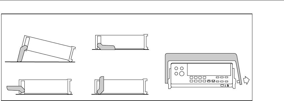
3. Carrying Position
1. Viewing Position
2. Alternate Viewing Position
4. Removal Position
(to Remove, Pull Ends Out)
Pull End Out and Towards You.
Then Slide to Left.
aam03f.eps
Figure 2-3. Adjusting Handle
If you have not already done so, plug the line cord into the connector on the rear of the
meter. The meter will operate on any line voltage between 90 V ac and 264 V ac without
adjustment, and any frequency between 45 and 440 Hz. However, it is only warranted to
meet published specifications at 50/60 Hz.
Turning the Meter on
To turn the meter on, press in the green, POWER button located on the lower-right of the
front panel. If the meter is being operated under battery power and you turn the meter off,
you must wait five seconds before turning the meter back on. If you do not, the meter will
not power-up.
When the meter is turned on, the primary and secondary displays light for about 4
seconds while the instrument performs an internal self-test of its digital circuitry. These
tests check RAM, ROM, A/ D, calibration, and the display. The meter has passed all tests
and is ready for normal operation if an error code is not displayed. However, if an error is
detected, the meter will still attempt to operate. (Refer to "Self-Test Diagnostics and
Error Codes" in Chapter 6.)
If any front panel button other than E is held down while the power-up sequence is in
progress, the entire display stays on until another button is pressed. Then, the powerup
sequence continues.
After the meter completes the power-up sequence, it assumes the power-up measurement
configuration stored in non-volatile memory. The power-up configuration set at the
factory is shown in Table 3-13. (To change the power-up configuration, refer to
"Changing the Power-Up Configuration" in Chapter 3.)
Using the Pushbuttons
The pushbuttons on the front panel select meter functions and operations. A summary of
basic pushbutton operations is shown in Figure 2-4.
Pushbuttons can be used in three ways. You can:
• Press a single button to select a function or operation.
EXAMPLE: Press Z to select volts ac for the primary display.
Press a combination of buttons, one after the other.