
user manual

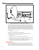
Table Of Contents
- 45 Dual Display Multimeter
- 1. Introduction
- 2. Getting Started
- 3. Operating the Meter From the Front Panel
- 4. Applications
- 5. Operating the Meter Using the Computer Interface
- Introduction
- Preparing the Meter for Operations via the RS-232 Interface
- Preparing the Meter to be Operated via IEEE-488 Interface
- Getting Started With An Installation Test
- How the Meter Processes Input
- How the Meter Processes Output
- Triggering Output
- Service Requests (IEEE-488 Only and Status Registers
- Computer Interface Command Set
- IEEE-488 Capabilities and Common Commands
- Function Commands and Queries
- Function Modifier Commands and Queries
- Range and Measurement Rate Commands and Queries
- Measurement Queries
- Compare Commands and Queries
- Trigger Configuration Commands
- Miscellaneous Commands and Queries
- RS-232 Remote/Local Configurations
- Sample Program Using the RS-232 Computer Interface
- Sample Programs Using the IEEE-488 Computer Interface
- 6. Maintenance
- Appendices
4-1
Chapter 4
Applications
Introduction
Chapter 4 discusses some applications that will help you use the meter effectively. These
applications assume you are familiar with the basic operation of the meter and have a
basic understanding of electronics. A sophisticated understanding of electrical circuits is
not necessary.
Using the Dual Display
Using the dual display effectively and with ingenuity can greatly enhance your test and
measurement capabilities. By allowing you to make several measurements on a particular
input signal, the dual display makes it easy to take measurements that in the past required
you to use two meters or make a series of measurements.
To see the ease with which the dual display can be used to take a reading of the ac
component of a signal on one display and its frequency on the other, perform the
following procedure to measure the voltage and frequency of line power:
1. Press in POWER to turn the meter on.
2. Plug the test leads into the X and COM input terminals.
3. Press Z to select volts ac for the primary display.
4. Press S , then press F to select frequency for the secondary display.
5. Insert the test lead probes into a wall socket. The display will appear something like
Figure 4-1.