
user manual
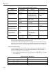
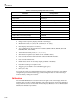

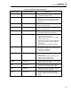
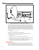
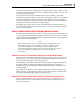
Table Of Contents
- 45 Dual Display Multimeter
- 1. Introduction
- 2. Getting Started
- 3. Operating the Meter From the Front Panel
- 4. Applications
- 5. Operating the Meter Using the Computer Interface
- Introduction
- Preparing the Meter for Operations via the RS-232 Interface
- Preparing the Meter to be Operated via IEEE-488 Interface
- Getting Started With An Installation Test
- How the Meter Processes Input
- How the Meter Processes Output
- Triggering Output
- Service Requests (IEEE-488 Only and Status Registers
- Computer Interface Command Set
- IEEE-488 Capabilities and Common Commands
- Function Commands and Queries
- Function Modifier Commands and Queries
- Range and Measurement Rate Commands and Queries
- Measurement Queries
- Compare Commands and Queries
- Trigger Configuration Commands
- Miscellaneous Commands and Queries
- RS-232 Remote/Local Configurations
- Sample Program Using the RS-232 Computer Interface
- Sample Programs Using the IEEE-488 Computer Interface
- 6. Maintenance
- Appendices
45
Users Manual
4-2
CAL
ENABLE
V
10A
100
mA
600V CAT I
1000V CAT I
FUSE F1
500 mA
F 250V
POWER
AUTO
2ND
MN MX
RATE
dB
REL
REF# LOCAL
THRESH ADDR BAUD
HOLD
LO
HI
COMP
A
A
V
FREQ
DUAL DISPLAY MULTIMETER
45
V
!
REF
FUSED
COM
+
-
FREQ
V
2ND
AUTO
VAC
Hz
M
aam16f.eps
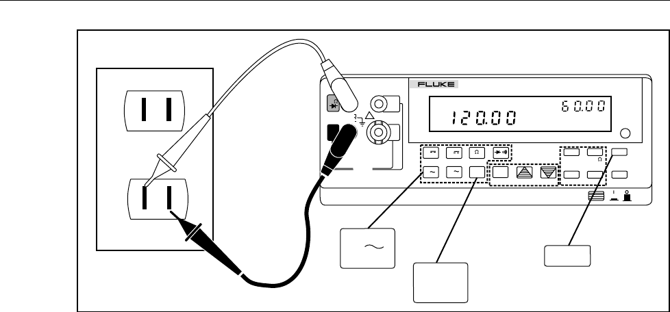
Figure 4-1. Dual Display Showing Volts AC and Frequency
Using Measurement Functions in Combination
The dual display allows you to display two properties of the input signal being measured.
Any combination of two properties from the list below is allowed, even those that may
not be useful:
Volts dc
Volts ac
Current dc
Current ac
Resistance
Frequency
Diode Test/Continuity
Note
Volts (dc + ac) rms or Current (dc + ac) rms measurements can only be
made in the primary display. While (dc + ac) measurements are being
made, another function cannot be selected for the secondary display.
Additional combinations of dual readings are added if you use the function modifiers—
i.e., REL, MN MX, HOLD, or dB.
Some applications of the dual display using common combinations of readings are
provided in Table 4-1.
Taking Voltage and Current Measurements Using the Dual Display
Most applications of the dual display listed in Table 4-1 can be performed using a single
set of test leads connected to the Xand COM input terminals.
However, to measure the voltage and current of an input signal requires three leads. Be
sure that the voltage and current measurements share the same common as shown in
Figure 4-2. Then simply follow the precautions you would follow if you were making
normal current measurements without a current clamp.