
user manual
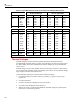

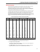
Table Of Contents
- 45 Dual Display Multimeter
- 1. Introduction
- 2. Getting Started
- 3. Operating the Meter From the Front Panel
- 4. Applications
- 5. Operating the Meter Using the Computer Interface
- Introduction
- Preparing the Meter for Operations via the RS-232 Interface
- Preparing the Meter to be Operated via IEEE-488 Interface
- Getting Started With An Installation Test
- How the Meter Processes Input
- How the Meter Processes Output
- Triggering Output
- Service Requests (IEEE-488 Only and Status Registers
- Computer Interface Command Set
- IEEE-488 Capabilities and Common Commands
- Function Commands and Queries
- Function Modifier Commands and Queries
- Range and Measurement Rate Commands and Queries
- Measurement Queries
- Compare Commands and Queries
- Trigger Configuration Commands
- Miscellaneous Commands and Queries
- RS-232 Remote/Local Configurations
- Sample Program Using the RS-232 Computer Interface
- Sample Programs Using the IEEE-488 Computer Interface
- 6. Maintenance
- Appendices
Applications
When Measuring Resistance
4
4-9
When Measuring Resistance
Two-Wire Configuration
The meter measures resistance in a two-wire configuration using a resistance ratio (some-
times called ratio-ohms) technique. Two-wire resistance measurements are simple to set
up and yield good results for most measurement conditions.
The full-scale voltage for each resistance range is shown in Table 4-5. The z input
test lead is positive with respect to the COM lead.
Correcting for Test Lead Resistance
The resistance of the test leads can introduce error when measuring low resistances. Typi-
cal test leads may add as much as 0.5 Ω to readings.
To correct for this error using the relative modifier (REL):
1. Insert test leads in the X and COM input terminals.
2. Turn the meter on and press O to select the resistance function.
3. Select the manual range mode by pressing E, T, or U . Then press U or
T to select the desired range. This is necessary because autoranging is turned off
(and the meter is locked in the range it is in) when the relative mode is selected.
4. Touch the test leads together. The display will show the resistance of the test leads.
5. With the test leads still touching, press K . The resistance in the test leads becomes
the relative base and the meter should show 0 Ω.
6. As long as the relative modifier remains selected, the resistance readings shown on
the display will be the resistance measured minus the relative base, which in this case
is the resistance in the test leads.
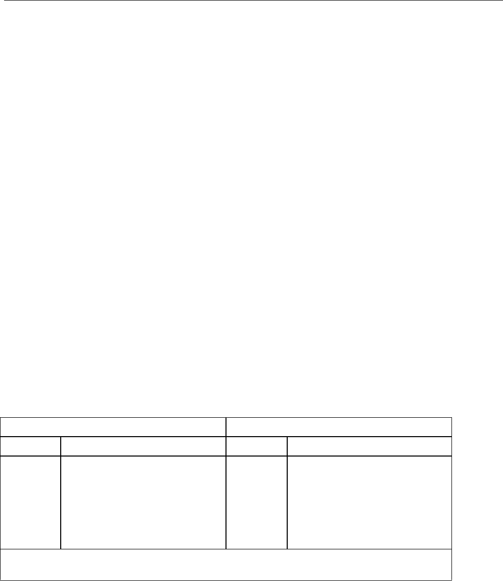
Table 4-5. Ohms Test Voltage
Medium and Fast Reading Rates Slow Reading Rate
Range Typical Full Scale Voltage Range Typical Full Scale Voltage
300 Ω
3 kΩ
30 kΩ
300 kΩ
3 MΩ
30 MΩ
300 MΩ
0.25
0.24
0.29
0.29
0.3
2.25
2.9
100 Ω
1000 Ω
10 kΩ
300 kΩ
1000 kΩ
10 MΩ
100 MΩ
0.09
0.10
0.11
0.11
0.12
0.65
2.75
Open circuit voltage is 3.2 V (maximum) on the 100 Ω, 300 Ω, 30 MΩ, 100 MΩ, and 300 MΩ ranges, and
1.5 V (maximum) on all other ranges.
True RMS Measurements
The meter measures the true rms value of ac voltages and currents. In physical terms, the
rms (root-mean-square) value of a waveform is the equivalent dc value that causes the
same amount of heat to be dissipated in a resistor. True rms measurement greatly
simplifies the analysis of complex ac signals. Since the rms value is the dc equivalent of
the original waveform, it provides a reliable basis for comparing dissimilar waveforms.