
user manual
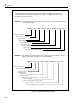
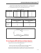
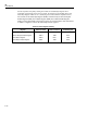
Table Of Contents
- 45 Dual Display Multimeter
- 1. Introduction
- 2. Getting Started
- 3. Operating the Meter From the Front Panel
- 4. Applications
- 5. Operating the Meter Using the Computer Interface
- Introduction
- Preparing the Meter for Operations via the RS-232 Interface
- Preparing the Meter to be Operated via IEEE-488 Interface
- Getting Started With An Installation Test
- How the Meter Processes Input
- How the Meter Processes Output
- Triggering Output
- Service Requests (IEEE-488 Only and Status Registers
- Computer Interface Command Set
- IEEE-488 Capabilities and Common Commands
- Function Commands and Queries
- Function Modifier Commands and Queries
- Range and Measurement Rate Commands and Queries
- Measurement Queries
- Compare Commands and Queries
- Trigger Configuration Commands
- Miscellaneous Commands and Queries
- RS-232 Remote/Local Configurations
- Sample Program Using the RS-232 Computer Interface
- Sample Programs Using the IEEE-488 Computer Interface
- 6. Maintenance
- Appendices

45
Users Manual
5-14
the bus responds to the poll by sending the contents of its Status Byte Register. If an
instrument on the bus has made a service request, the request service bit (RQS, bit 6) of its
Status Byte Register will be set to 1, identifying it as an instrument that requested service.
The contents of the Status Byte Register (STB) is determined by the Service Request
Enable Register (SRE), Event Status Register (ESR), Event Status Enable Register
(ESE), and the output buffer. These status registers are discussed below and summarized
in Table 5-5. Figure 5-3 shows the relationship of these registers.
Table 5-5. Status Register Summary
Register Read Command Write Command Enable Register
Status Byte Register
Service Request Enable Register
Event Status Register
Event Status Enable Register
*STB?
*SRE?
*ESR?
*ESE?
None
*SRE
None
*ESE
SRE
None
ESE
None