
user manual

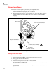
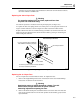
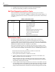
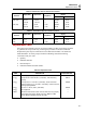
Table Of Contents
- 45 Dual Display Multimeter
- 1. Introduction
- 2. Getting Started
- 3. Operating the Meter From the Front Panel
- 4. Applications
- 5. Operating the Meter Using the Computer Interface
- Introduction
- Preparing the Meter for Operations via the RS-232 Interface
- Preparing the Meter to be Operated via IEEE-488 Interface
- Getting Started With An Installation Test
- How the Meter Processes Input
- How the Meter Processes Output
- Triggering Output
- Service Requests (IEEE-488 Only and Status Registers
- Computer Interface Command Set
- IEEE-488 Capabilities and Common Commands
- Function Commands and Queries
- Function Modifier Commands and Queries
- Range and Measurement Rate Commands and Queries
- Measurement Queries
- Compare Commands and Queries
- Trigger Configuration Commands
- Miscellaneous Commands and Queries
- RS-232 Remote/Local Configurations
- Sample Program Using the RS-232 Computer Interface
- Sample Programs Using the IEEE-488 Computer Interface
- 6. Maintenance
- Appendices
Maintenance
Current Input Fuses
6
6-3
If the fuse is good, the meter will read between .04 Ω and 1.0 Ω. If the fuse is blown,
the meter will read >10 MΩ to OL.
Replacing the 100 mA Input Fuse
W Warning
For protection against fire or arc flash, replace a blown fuse
only with one of identical rating.
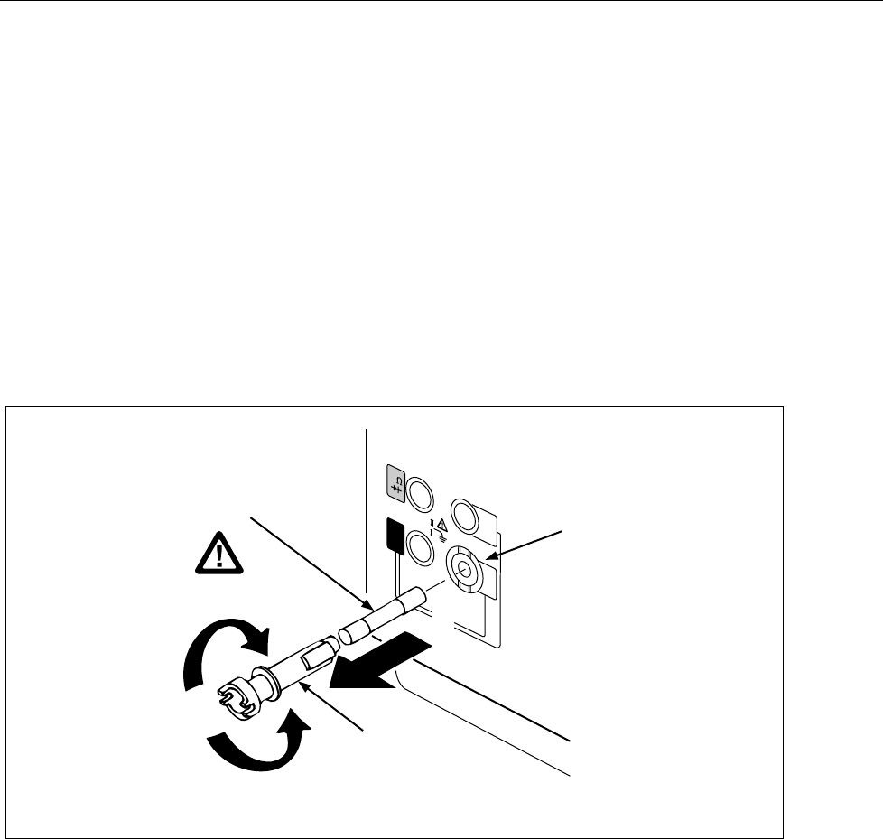
The 100 mA input fuse is mounted in the front panel input jack (see Figure 6-2).
To replace this fuse, first unplug the line cord. Then press in on the input jack and turn it 90
degrees counter-clockwise as shown in Figure 6-2. Slide out the fuse holder and fuse.
Replace a blown fuse with one of identical rating (see Table 6-5) and reinsert the fuse and
holder into the input terminal socket. Secure the fuse holder by pressing in and turning the
holder 90 degrees clockwise.
1000V CAT
FUSE F1
500 mA
F 250V
FUSED
600V CAT
10A
100
mA
V
COM
Front Panel Input Terminal
100 mA Input Socket
Fuse Holder
To remove, push in and turn counter clockwise.
To insert, reverse this procedure.
F1 Fuse (500 mA, 250V, Fast Blow)
1500 A Minimum Breaking Capacity
qb13f.eps
Figure 6-2. Replacing the 100 mA Input Fuse
Replacing the 10 A Input Fuse
The 10 A input fuse is located inside the meter. To replace the fuse:
1. Remove the single Phillips-head screw on the bottom of the case and the Phillips -
head screw on each side of the rear bezel.
W Warning
Opening the case may expose hazardous voltages. To avoid
electric shock, always disconnect the power cord and
measuring inputs before opening the case.
2. Remove the bezel and slip the case back from the front of the meter. The fuse and
fuse clip are visible at the front of the main printed circuit assembly (pca) near the
input terminals.