Doc No: OMM50000903 Rev: B Page 1 of 65 OPERATION AND MAINTENANCE MANUAL, L06 THROUGH L16 TRIPLEX PUMPS Rev ECN No. Date Reviewed By Approved By Status B 5018139 29-MAY-2007 Lyon, Tim Singleterry, Ronald RELEASED Summary: This is a manual for FMC L06 through L16 triplex piston pumps. These pumps include direct drive (no pinion shaft) and pinion drive (for internal gear reduction) and have a stroke length ranging from 1.50” through 4.00”.
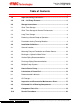
Doc No: OMM50000903 Rev: B Page 2 of 65 Table of Contents Section Title Page 1.0 Important Safety Instructions .................................................... 5 2.0 L06 – L16 Pump Features ........................................................... 6 3.0 Storage Instructions ................................................................... 8 3.1 Short Term Storage....................................................................... 8 3.2 Short Term Storage for Severe Environments .....
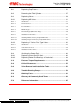
Doc No: OMM50000903 Rev: B Page 3 of 65 10.1 Replacing Cup Pistons................................................................ 23 10.2 Removing the Fluid Cylinder ....................................................... 27 10.3 Replacing Valves ........................................................................ 29 10.3.1 Replacing AR Valves .................................................................. 31 10.3.1.1 Introduction.............................................................
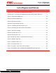
Doc No: OMM50000903 Rev: B Page 4 of 65 List of Figures and Pictures Figures Page Figure 1: L11 – L16 Pump Assembly with Pinion Shaft.....................................................6 Figure 2: L06 – L16 Pump Assembly with No Pinion Shaft (Includes HD & HV) ...............7 Figure 3: Power End Components..................................................................................19 Figure 4: Fluid End Components ....................................................................................
Doc No: OMM50000903 Rev: B Page 5 of 65 1.0 Important Safety Instructions WARNING: Many accidents occur every year through careless use of mechanical equipment. You can avoid hazards associated with high pressure equipment by always following the safety precautions listed below. • SHUT DOWN OR DISENGAGE the pump and all accessory equipment before attempting any type of service. Failure to do this could cause electrical shock or injury from moving pump parts or components under high pressure.
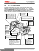
Doc No: OMM50000903 Rev: B Page 6 of 65 2.0 L06 – L16 Pump Features Exceptional design, workmanship, materials, and over 100 years of pump building experience are features you’ll find built into every FMC pump.
Doc No: OMM50000903 Rev: B Page 7 of 65 Choice of straight keyed shaft or mounting flange for direct coupling (splined shaft) of hydraulic motors (shown). Oil level sight gage allows remote monitoring of oil level and condition. Heavy-duty power ends are machined from a onepiece gray iron casting for long trouble free life. All pumps incorporate a reliable splash lube system with gravity feed return to sump.
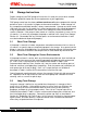
Doc No: OMM50000903 Rev: B Page 8 of 65 3.0 Storage Instructions Proper storage of your FMC pump will insure that it is ready for service when needed. Follow the guidelines below that fit the requirements of your application. FMC pumps come from the factory without crankcase oil and are prepared for storage periods of up to six (6) months in proper environmental conditions. Indoor storage in a dry, temperature-controlled location is always recommended.
Doc No: OMM50000903 Rev: B Page 9 of 65 Drain the oil from the pump power end. Remove the rear cover to expose the drive components. Spray all internal parts with a rust preservative that is soluble in lubricating oil while rotating the driveshaft several turns by hand to insure complete coverage. Replace the rear cover and add ½ to 1 cup of internal rust inhibitor described in Table 2.
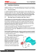
Doc No: OMM50000903 Rev: B Page 10 of 65 4.0 Installation Guidelines A proper installation is essential to optimal performance, long service life, and reduced maintenance requirements. Take time to thoroughly plan all aspects of your installation. 4.1 General Location It is important to position the pump on as flat and level a surface as possible to assist the splash oil lubrication system. Park mobile equipment, such as sewer cleaner trucks or drilling machines, on as level a surface as possible.
Doc No: OMM50000903 Rev: B Page 11 of 65 the motor. Install the o-ring around the pilot diameter on the mounting face of the motor. Lubricate the o-ring with hydraulic fluid or o-ring lubricant to ease assembly in the mounting flange/bearing housing. Clean the inside of the mounting flange/bearing housing and motor face to remove any dirt or debris. Insert the hydraulic motor into the mounting flange/bearing housing.
Doc No: OMM50000903 Rev: B Page 12 of 65 model are provided on the product data sheets available through FMC or your authorized FMC reseller. FMC does not recommend using the pump in static lift conditions without prior factory approval. 4.5 Discharge Piping Recommendations 1. Route the discharge piping in as short and direct a route as possible. Use the same pipe size as the outlet of the pump.
Doc No: OMM50000903 Rev: B Page 13 of 65 discharge line or between the pump and relief valve. FMC recommends that the discharge be returned to the tank or drain, not back into the pump suction line. 5. It is recommended that a start-up bypass line and valve be installed to allow flow to bypass the relief valve. This allows the pump to start in an unloaded condition (no discharge pressure). 4.
Doc No: OMM50000903 Rev: B Page 14 of 65 3. If accessible, check the piston rods to insure that they are free from abrasive particles or debris. Apply a light oil film to the piston rods before start up. 4. Insure that the pressure relief valve and all accessory equipment have been installed and properly adjusted. Verify that all joints are pressure tight. 5. Open the suction line valve to allow fluid to enter pump.
Doc No: OMM50000903 Rev: B Page 15 of 65 6.2 Oil Changes • Oil changes must be carried out after first 100 hours of operation, and subsequently after every 2500 hours or at least every 12 months. These intervals may be modified depending on actual operating conditions. • Oil should be changed when hot to prevent build up of sludge deposits. • It is advisable to check oil level at least once per month. If more than 10% of the total capacity has to be added, check for oil leaks.
Doc No: OMM50000903 Rev: B Page 16 of 65 RECOMMENDED LUBRICANT CHART - L06 THROUGH L12 Motor Oil Lubricant Type of Service General Service ISO Ambient SAE Viscosity SSU Temp Grade (cSt@40 C) Viscosity 0F to 100 F 30 100 100 F to 130 F 0F to -30 F Manufacturer Brand Name 90.0@40 Shell® Rotella T 15.0@100 Synthetic SAE 5W-40 99.1@40 Mobil® SCH 627 13.
Doc No: OMM50000903 Rev: B Page 17 of 65 7.0 Inspection and Preventative Maintenance Chart Routine maintenance is an essential part of any successful pump installation. Properly maintained FMC pumps are designed to offer years of trouble-free service. Regular maintenance and inspection will keep your pump operating at peak performance. FMC pumps have been carefully engineered to minimize maintenance requirements and simplify these tasks when they are required.
Doc No: OMM50000903 Rev: B Page 18 of 65 8.0 Estimated Life of Wearing Components The information given here is an estimate of the average wear life of listed components in clean liquid service. It is not a guarantee of life for any given application, but is intended to facilitate maintenance schedules and stocking of spares. The maintenance of the power end lubrication system will influence the life of the power end components.
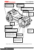
Doc No: OMM50000903 Rev: B Page 19 of 65 9.0 Component Parts List A typical pump configuration is shown below for general reference purposes. This will aid in identifying components for service procedures outlined in the following sections. Each size “L” series pump may have a slightly different appearance. The Industrial Pump models have a pinion shaft for internal gear reduction.
Doc No: OMM50000903 Rev: B Page 20 of 65 Figure 4: Fluid End Components The illustrations above depict a typical pump with disc valves, and Type A piston cups. Alternate construction “threaded” style valve covers and Type B style pistons may be used on some models. The service procedures outlined in this manual are intended to describe the more popular type of pump. Other configurations and minor design differences may exist with alternate pumps.
Doc No: OMM50000903 Rev: B Page 21 of 65 Component Description Item No.
Doc No: OMM50000903 Rev: B Page 22 of 65 Item No.
Doc No: OMM50000903 Rev: B Page 23 of 65 10.0 Service Procedures FMC pumps are designed to simplify all required maintenance. The following sections illustrate step-by-step instructions for performing most common service procedures of a pump. Read each section before starting service work on the pump. Refer to Figures 3 and 4 for location of components. WARNING: 10.1 Many accidents occur every year through careless use or service of mechanical equipment.
Doc No: OMM50000903 Rev: B Page 24 of 65 1. It is recommended that a sufficient quantity of clean water be pumped through the fluid end before starting any service procedures that involve fluid end components. This will remove a significant portion of contaminants left in the fluid cylinder by the normal pumpage and improve the ability to work with parts or see potential problems. 2. Bleed off all pressure inside pump fluid end before starting any service work.
Doc No: OMM50000903 Rev: B Page 25 of 65 6. Using a socket wrench with a long extension, remove the hex piston nut (42) from the piston/crosshead rod (7). This nut secures the piston assembly to the piston/crosshead rod. 7. Following the hex piston nut (42) removal, use the FMC piston tool (A5049) to pull the piston assembly from the cylinder (39). Insert the FMC piston tool inside the cylinder until flush with the face of the slotted piston retainer nut (43).
Doc No: OMM50000903 Rev: B Page 26 of 65 10. Inspect all parts for damage or unusual wear. Insure that the interior surface of the cylinder (39) is smooth and free of cracks or grooves. New piston cups (40) will fail prematurely if installed in liners with damaged bores. FMC strongly recommends that all three piston cups be replaced, not just those that show signs of leakage, whenever this type of service is performed. This will maximize operational time between service intervals. 11.
Doc No: OMM50000903 Rev: B Page 27 of 65 10.2 Removing the Fluid Cylinder NOTE: The fluid cylinder (37) may be removed to inspect for internal damage, to be repaired, to replace the fluid cylinder, to replace damaged cylinders, cylinder o-rings, or to service piston rod seals. Some L06 pumps require fluid cylinder removal to service the pistons. Refer to Figure 4 for illustration of parts. 1.
Doc No: OMM50000903 Rev: B Page 28 of 65 7. Always replace the cylinder gaskets (48) when the cylinders have been moved or replaced. 8. Installation will be the reverse of this procedure. 9. Torque all fasteners as outlined in the Fastener Torque Requirements, Section 11.0 of this manual. Please note that if the nuts (61) on the fluid cylinder studs (59) are not properly torqued, a failure is likely.
Doc No: OMM50000903 Rev: B Page 29 of 65 10.3 Replacing Valves 1. Three types of valves may be supplied with various models of the “L” series pumps. They are disc type valves, AR style valves, and ball type valves. The next steps must be performed for each type of valve. 2. A minimum of approximately 2 feet of clearance is required above, below, and in front of the pump fluid cylinder to allow valve service without removal of the fluid end.
Doc No: OMM50000903 Rev: B Page 30 of 65 6. For AR valves refer to section 10.3.1. This document describes the methods for removing and installing the AR valves. 7. For disc valves refer to section 10.3.2. This document describes the methods for removing and installing disc valves. 8. For ball valves, also refer to section 10.3.2. However, the balls are not retained in the valve seat. The ball can easily be removed from the valve assembly by lifting it out of the open cage portion of the valve seat.
Doc No: OMM50000903 Rev: B Page 31 of 65 10.3.1 10.3.1.1 Replacing AR Valves Introduction The AR, Abrasion Resistant, valve is a durable wing-guided, spring-loaded check valve. It is used with abrasive fluids, bentonite mud, water, oil etc., and provides excellent performance and long service life. A typical valve is shown in Figure 5 with valve components identified in the exploded view to the right.
Doc No: OMM50000903 Rev: B Page 32 of 65 10.3.1.2 Knock Out Tool The simplest of the tools is the removal and installation tool, part number P504436. It is used primarily on the M06 and L06 model pumps for small valves. To remove a valve, this tool is inserted from the bottom of the fluid cylinder and is stopped by the bottom of the valve seat. The tool is struck sharply with a hammer and the valve is loosened.
Doc No: OMM50000903 Rev: B Page 33 of 65 Picture 1: Removing the valve from the seat Picture 2: Removing the valve from the fluid cylinder Subject to contractual terms and conditions to the contrary, this document and all the information contained herein are the confidential and exclusive property of FMC Technologies, and may not be reproduced, disclosed, or made public in any manner prior to express written authorization by FMC.
Doc No: OMM50000903 Rev: B Page 34 of 65 10.3.1.3 Eccentric Discs The second style of tool is more complex but capable of exerting more force on the valve than the Knock Out Tool. This style can be used on all sizes of the AR valves in all of the pump models. The discharge valve is removed first. The valve must be disassembled with the cage, spring and valve body removed from the fluid cylinder prior to the seat being pulled. A special hex drive tool will assist in removing the cage from the seat.
Doc No: OMM50000903 Rev: B Page 35 of 65 This style of tool includes a disc that passes through the seat to allow force to be placed underneath it. The disc has a threaded hole that is at the center of the disc (concentric disc). A tension rod is threaded into the hole. The second disc has an eccentric hole with clearance for the tension rod and sits on top of the threaded disc. This keeps the threaded disc engaged with the edge of the seat.
Doc No: OMM50000903 Rev: B Page 36 of 65 Nut Stop Bumper Tension nut Strong Back Tension Rod Valve Seat with cage, spring and valve body removed Eccentric Discs Figure 9: Removing the seat Subject to contractual terms and conditions to the contrary, this document and all the information contained herein are the confidential and exclusive property of FMC Technologies, and may not be reproduced, disclosed, or made public in any manner prior to express written authorization by FMC.
Doc No: OMM50000903 Rev: B Page 37 of 65 A variation of this is the use of a hydraulic pump and cylinder jack (porta power) to generate the load that the bumper, strong back, and nut would generate. This is shown if Figure 8. It is useful to put “dry ice” on the seat if it will not loosen. Allow five minutes for cooling of seat before attempting removal. CAUTION: Dry ice will cause freeze burns to skin if contacted. Use thick leather gloves when handling. Dry ice is often available at grocery stores.
Doc No: OMM50000903 Rev: B Page 38 of 65 10.3.1.4 Mandrel Type This is a variation of the Eccentric Disc type. It can be used on all sizes of valves. It has a more uniform loading of the seat than the Eccentric Disc type and therefore more pulling capacity. A unique size is required for each valve size and the cost is usually higher than the Eccentric Disc. Refer to Picture 3 to see a typical mandrel type tool.
Doc No: OMM50000903 Rev: B Page 39 of 65 Threads on the inside diameter to connect to the tension member Threaded Mandrel O-Rings Valve Seat, Fluid Cylinder not shown Expanding Collets Figure 11: Mandrel Tool in use The lower part of the mandrel and the collets are passed through the valve seat and then slid down the mandrel to expand them. The o-rings keep the collets on the mandrel. The tension is applied in the same way as was done for the Eccentric Disc type.
Doc No: OMM50000903 Rev: B Page 40 of 65 10.3.1.5 Threaded Type (AR Valves Only) The threaded type can only be used on valves that have the through bore of the seat threaded prior to installation. The load capacity is similar to the Mandrel Type but it is simpler to use. This is the last variation of methods of applying tension to the valve seat to remove it from the fluid cylinder.
Doc No: OMM50000903 Rev: B Page 41 of 65 10.3.1.6 Installation of AR Valves AR valves are installed differently depending on their size. Larger valves are assembled at the factory with the cage screwed on hand-tight before shipping while smaller valves are tightened with a torque wrench to final specifications. Follow the instructions in section 10.3.1.6.1 for all series 3 and 23 valves as well as valve part numbers 3267652 and P533637. See section 10.3.1.6.2 for all larger AR valves. 10.3.1.6.
Doc No: OMM50000903 Rev: B Page 42 of 65 10.3.1.6.2 Installing Larger, Non-Factory Torqued AR Valves The suction valve must be installed before the discharge valves. The following reassembly procedure is applicable for both. 1. Select a new valve seat. Disassembly of a new valve assembly may be necessary. Do not install complete assembled valves. 2. Carefully clean the taper in the fluid cylinder and on the valve seat with a cleaning solution and a clean cloth.
Doc No: OMM50000903 Rev: B Page 43 of 65 10.3.2 10.3.2.1 Replacing “L” Series Disc Type Valves Introduction The disc type valve used in “L” series FMC pump models is shown in Figure 13. The standard construction of stainless steel seat, disc, and stop are a cost effective design with excellent performance and ample life. These valve assemblies come preassembled from the factory and should not need to be disassembled.
Doc No: OMM50000903 Rev: B Page 44 of 65 10.3.2.2 Valve Removal Tools There are three (3) Knock Out tools available for removing valves from “L” series pumps. The P534695 Small Ball Knock Out tool is the preferred tool for the smaller valves in the L06 and L09 pumps. The P504436 Knock Out tool can also be used on the smaller valves in the L06 and L09 pumps. The P534694 Large Ball Knock Out tool is designed for the larger valves in the L11 through L16 pumps.
Doc No: OMM50000903 Rev: B Page 45 of 65 10.3.2.3 Installation of Disc Valves The suction valves must be installed before the discharge valves can be installed. The following reassembly procedure is applicable for both. 1. Select a new valve assembly and check to insure the taper on the valve is clean. 2. Carefully clean the taper in the fluid cylinder and on the valve seat with a cleaning solution and a clean cloth. Small scratches can be removed with steel wool or 100 grit emery paper.
Doc No: OMM50000903 Rev: B Page 46 of 65 10.4 Servicing the Power End 10.4.1 Replacing Piston Rod Oil Seals NOTE: Insure that all pressure inside the pump fluid cylinder has been bled off before starting any service work. CAUTION: CHECK TO INSURE THAT THE POWER IS LOCKED OUT AND TAGGED OUT. 1. The piston rod oil seals (9) retain oil in the power end and prevent contamination from entering the power end by way of the piston rods.
Doc No: OMM50000903 Rev: B Page 47 of 65 5. To rebuild, insert new seals (9) in the seal holder (8), taking care to insure they are oriented in the same manner as the ones that were removed. Do not reuse seals that have been removed from the pump. Replace the seal retainer gasket (11) if it shows signs of deformation or damage. 6. Wrap tape or other material over the exposed piston rod threads to protect the new seal lips from damage.
Doc No: OMM50000903 Rev: B Page 48 of 65 10.4.2 Replacing Power End Bearings & Crankshaft WARNING: Disconnect the driver from the pump and insure that suction and discharge lines are disconnected or blocked and have no pressure applied. 1. Removal of the fluid cylinder simplifies crankshaft removal on L16 pump models. 2. Remove magnetic pipe plug (32) to allow all oil to drain from power frame (1). 3. Remove all rear cover cap screws (29).
Doc No: OMM50000903 Rev: B Page 49 of 65 6. NOTE: Connecting rods and caps are matched sets and must always be reassembled with their original mate and in the same orientation. Note the numbered codes stamped on each half of the connecting rod assemblies and make certain they are installed as matched set and in the same orientation when re-assembling the pump. 7.
Doc No: OMM50000903 Rev: B Page 50 of 65 12. Remove the hex head cap screws (28), bearing housings (12 and 36), and shims (13) from both sides of the pump. Count and record the shims on each side to facilitate assembly. The gaskets (14) may adhere to the power frame surface and can be left in place if they are not damaged. For pump models that use o-ring seals it is recommended that the o-rings be replaced. The bearing cups (23) will remain in the bearing housing.
Doc No: OMM50000903 Rev: B Page 51 of 65 15. Bearing cones (22) may be removed from the crankshaft using an automotive type bearing puller. Bearing cups (23) can be removed from the bearing housing using a puller if a sufficient lip is available for the puller arms to grab. An alternate procedure involves running a weld bead around the inside surface of the cup. When cool, this will reduce the interference between the cup and bearing housing enough to free the cup.
Doc No: OMM50000903 Rev: B Page 52 of 65 22. To replace the tapered roller bearings on the crankshaft, heat the cones to a maximum of 300° F (149° C). Slide them down the shaft unit they are full seated against shoulder. The hot cone may pull away from the shoulder unless it is held in position until it cools enough to grab the shaft. Use a .001” thick feeler gauge to insure the cone is fully seated against the shoulder after parts have cooled. 23.
Doc No: OMM50000903 Rev: B Page 53 of 65 31. Move the crankshaft to one side of the power frame using a light tap from a rubber mallet or a pry bar. Rotate the crankshaft several turns and repeat the light taps from a rubber mallet or the use of a pry bar to insure the crankshaft is to one side. 32. Mount indicator base on the power frame with the indicator tip on a machined shoulder surface of the crankshaft (do not measure from a cast surface) and the axis of the indicator parallel to the crankshaft.
Doc No: OMM50000903 Rev: B Page 54 of 65 11.0 Fastener Torque Requirements NOTICE: No pump service procedure is complete without insuring that the fasteners have been properly torqued. Failure to properly tighten the pump bolts could cause the pump to leak or possibly allow the pump to fail. Always use a calibrated torque wrench during the installation of all critical fasteners listed in Table 4 below. Values are in footpounds (Ft-lb) and Newton meters (N-m). Typical sizes are shown in Table 4 below.
Doc No: OMM50000903 Rev: B Page 55 of 65 SIZE 0.500 0.625 0.750 0.875 1.000 1.125 1.250 Ft-lb 40 80 135 215 320 460 630 (N-m) 54 108 183 292 434 624 854 Table 5: Torque Values for Xylan-Coated Fasteners 12.0 Critical Clearances When maintenance requiring disassembly of the power end is performed, the following clearances should be checked to see if they are within factory specification or within maximum allowable limits. Additional clearance is allowed for component wear.
Doc No: OMM50000903 Rev: B Page 56 of 65 13.0 Valve Removal and Installation Tools Table 7 shows the FMC part numbers for valve removal tools for the various AR valves used in the models specified. Table 8 on the following page shows the FMC part numbers for valve removal and installation tools for the various Disc valves used.
Doc No: OMM50000903 Rev: B Page 57 of 65 L06 SIZE PUMPS VALVE TYPE Disc Disc Disc Disc Disc Disc VALVE ASSY 5257290 5257291 5272584 5272585 P506665 P506666 VALVE SIZE 1.312 G.L. / .94 ID 1.437 G.L. / .94 ID 1.312 G.L. / .94 ID 1.437 G.L. / .94 ID 1.437 G.L. / .94 ID 1.312 G.L. / .
Doc No: OMM50000903 Rev: B Page 58 of 65 14.0 Trouble-Shooting Pumps This chart is designed to aid in the solution of pump and pump system problems. Once the problem has been identified, work through the possible causes and solutions until the problem has been corrected.
Doc No: OMM50000903 Rev: B Page 59 of 65 Pump runs rough, knocks, or vibrates (ONLY) -Broken or weak valve spring -Valve damaged or unseated -Loose plunger, piston, or rod -Low oil level in power end -Excessive connecting rod bearing clearance -Excessive main bearing clearance -Worn wrist pin or bearing -Pump running backward -Loose sheaves or bushings (v-belt drive) -Gear tooth cracked or broken -Insufficient NPSHA -Excessive acceleration head in suction line -Pulsation dampener improperly charged -Inlet
Doc No: OMM50000903 Rev: B Page 60 of 65 Fluid leaking from pump -Piston cups are worn -Piston to rod o-ring damaged -Fluid cylinder bolts not properly tightened -Fluid cylinder o-rings (or gaskets) damaged -Replace piston cup -Replace o-ring -Properly tighten and torque bolts -Replace damaged o-rings or gaskets Reduced packing or piston cup life -Highly abrasive particles in fluid -Packing or piston cups run dry -Incorrect packing or cups for fluid type -Inadequate packing lubrication -Pump was run dry
Doc No: OMM50000903 Rev: B Page 61 of 65 15.0 Ordering Parts Service parts are available through FMC’s worldwide network of distributors or from the original supplier for the equipment that the pump is a component of. If unsure where to purchase parts, contact FMC customer service for the location of an authorized parts retailer in your area. Always insist on genuine FMC replacement parts.
Doc No: OMM50000903 Rev: B Page 62 of 65 16.0 Glossary of Commonly Used Terms CAPACITY The total volume throughput per unit of time at suction conditions. It includes both liquid and any dissolved or entrained gases. For all practical purposes this can be considered the volume flow rate in the suction pipe. The standard unit of pump capacity is U.S. gallons per minute (GPM) and metric cubic meters per hour (m3/hr).
Doc No: OMM50000903 Rev: B Page 63 of 65 FLOODED SUCTION Implies that the level of liquid in the suction vessel is above the centerline of the suction port of the pump. FLUID END The portion of the pump that converts the linear motion supplied by the power end into fluid flow at pressure. This may also be called the Liquid End. It is called a valve chamber in old literature. NPSHa An abbreviation that stands for Net Positive Suction Head Available.
Doc No: OMM50000903 Rev: B Page 64 of 65 STROKE LENGTH The length of one complete, unidirectional motion of the piston or plunger. Stroke length is usually expressed in inches. PUMP VALVE A check valve that allows flow of liquid in one direction. FMC pumps have a series of two valves, one suction (inlet) and one discharge, per pumping cylinder.
Doc No: OMM50000903 Rev: B Page 65 of 65 17.0 Reference Information Use the following section to record key information about your specific pump model. Information such as part and serial numbers will be needed when ordering service parts. This data may be found stamped on the metal nameplate located on the pump power frame. This area may also be used to make notations about special parts, procedures, phone numbers, or other important information related to your pump.