
Water Pump User Manual

Doc No: OMM50000903
Rev: B Page 4 of 65
Subject to contractual terms and conditions to the contrary, this document and all the information contained herein are the confidential and exclusive
property of FMC Technologies, and may not be reproduced, disclosed, or made public in any manner prior to express written authorization by FMC.
List of Figures and Pictures
Figures Page
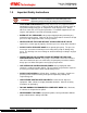
Figure 1: L11 – L16 Pump Assembly with Pinion Shaft.....................................................6
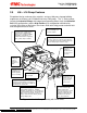
Figure 2: L06 – L16 Pump Assembly with No Pinion Shaft (Includes HD & HV) ...............7
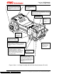
Figure 3: Power End Components..................................................................................19
Figure 4: Fluid End Components....................................................................................20
Figure 5: AR Valve Assembly.........................................................................................31
Figure 6: Using the Knock Out Tool................................................................................32
Picture 1: Removing the valve from the seat...................................................................33
Picture 2: Removing the valve from the fluid cylinder......................................................33
Figure 7: Valve Disassembly ..........................................................................................34
Figure 8: Eccentric Disc in Use.......................................................................................35
Figure 9: Removing the seat...........................................................................................36
Figure 10: Hydraulic Power used to Remove Valve Seat................................................37
Picture 3: Mandrel Type Tool..........................................................................................38
Figure 11: Mandrel Tool in use.......................................................................................39
Figure 12: Threaded Tool in use.....................................................................................40
Figure 13: Typical L Series Disc Valve Assembly...........................................................43
Figure 14: Illustration of the P534694 and P534695 Ball Knock Out Tools .....................44