UNVENTED (VENT-FREE) GAS LOG HEATER OWNER’S OPERATION AND INSTALLATION MANUAL PFS FLAME-MAX® Multi-Sided Log Design ® US Patent Pending FVFM27NR, FVFM27PR, VYM27NR and VYM27PR Remote Control Ready Models Also Design-Certified As A Vented Decorative Appliance WARNING: If the information in this manual is not followed exactly, a fire or explosion may result causing property damage, personal injury or loss of life.
Table of Contents Safety................................................................... 2 Product Identification............................................ 5 Local Codes......................................................... 5 Unpacking............................................................ 5 Product Features.................................................. 5 Remote Control Accessories................................ 6 Air for Combustion and Ventilation....................... 6 Installation....
Safety Continued DANGER: Carbon monoxide poisoning may lead to death! Carbon Monoxide Poisoning: Early signs of carbon monoxide poisoning resemble the flu, with headaches, dizziness, or nausea. If you have these signs, the heater may not be working properly. Get fresh air at once! Have heater serviced. Some people are more affected by carbon monoxide than others. These include pregnant women, people with heart or lung disease or anemia, those under the influence of alcohol, and those at high altitudes.
SAFETY Continued 4. If you smell gas • shut off gas supply • do not try to light any appliance • do not touch any electrical switch; do not use any phone in your building • immediately call your gas supplier from a neighbor’s phone. Follow the gas supplier’s instructions • if you cannot reach your gas supplier, call the fire department 5. This heater shall not be installed in a bedroom or bathroom unless installed as a vented appliance (see Installing Damper Clamp Accessory for Vented Operation, page 11).
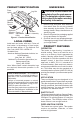
Product Identification Piezo Ignitor Log Set Optional Remote Control Optional Base Selector Flame Switch Adjustment Control Assembly Knob Knob Figure 1 - Product Identification Local Codes Install and use heater with care. Follow all local codes. In the absence of local codes, use the latest edition of The National Fuel Gas Code, ANSI Z223.1/NFPA 54*. *Available from: American National Standards Institute, Inc. 1430 Broadway New York, NY 10018 National Fire Protection Association, Inc.
Remote Control Accessories There are 4 optional controls that can be purchased separately for this log heater: • wall switch • wall thermostat • hand-held ON/OFF remote • hand-held thermostat remote See Accessories, page 29. Note: The wall thermostat or hand-held thermostat may not be used where vented decorative listing is required.
AIR FOR COMBUSTION AND VENTILATION Continued DETERMINING FRESH-AIR FLOW FOR HEATER LOCATION Determining if You Have a Confined or Unconfined Space Use this work sheet to determine if you have a confined or unconfined space. Space: Includes the room in which you will install heater plus any adjoining rooms with doorless passageways or ventilation grills between the rooms. 1. Determine the volume of the space (length x width x height). Length x Width x Height =___________ c u . ft.
AIR FOR COMBUSTION AND VENTILATION Continued 12" Ventilation Grills Into Adjoining Room, Option 1 Ventilation Grills Into Adjoining Room, Option 2 Or Remove Door into Adjoining Room, Option 3 items directly to the outdoors or spaces open to the outdoors. These spaces include attics and crawl spaces. Follow the National Fuel Gas Code, ANSI Z223.1/NFPA 54, Air for Combustion and Ventilation for required size of ventilation grills or ducts.
INSTALLATION Continued WARNING: Never install the heater • in a bedroom or bathroom unless installed as a vented appliance, see page 12 • in a recreational vehicle • where curtains, furniture, clothing, or other flammable objects are less than 42" from the front, top, or sides of the heater • in high traffic areas • in windy or drafty areas CAUTION: This heater creates warm air currents. These currents move heat to wall surfaces next to heater.
INSTALLATION Continued NOTICE: Manual control heaters may be used as a vented product. If so, you must always run heater with chimney flue damper open. If running heater with damper open, noncombustible material above fireplace opening is not needed. Go to Installing Damper Clamp Accessory for Vented Operation, page 12.
INSTALLATION Continued Mantel Shelf 10" Underside of Mantel Shelf 8" 6" 2 1/2" Minimum Noncombustible Material All minimum distances are in inches (A) 12" 18" 20" 22" 24" Minimum Distances to Noncombustible Underside of Material Height Mantel Top of Fireplace Opening Figure 6 - Minimum Mantel Clearances Without Using Hood 12" Mantel Shelf 10" Underside of Mantel Shelf 8" 6" Minimum Noncombustible Material 2½" 8" 12" 15" Min.
INSTALLATION Continued Mantel Clearances In addition to meeting noncombustible material clearances, you must also meet required clearances between fireplace openings and mantel shelf on each side of the fireplace. If you do not meet the clearances listed below, you will need a hood. Determining Minimum Mantel Clearance If you meet minimum clearance between mantel shelf and top of fireplace opening, a hood is not required (see Figure 6, page 11).
INSTALLATION Continued See chart below for minimum permanent flue opening you must provide. Attach damper clamp so the minimum permanent flue opening will be maintained at all times. Chimney Height Minimum Permanent Flue Opening 6' to 15' 15' to 30' 39 sq. inches 29 sq. inches Area of Various Standard Round Flues Diameter Area 5" 6" 7" 8" 20 sq. inches 29 sq. inches 39 sq. inches 51 sq.
INSTALLATION Continued 3. Place heater base in fireplace. 4. Place logs in their proper position on heater base. See Installing Logs, page 17. 5. Center heater base and logs front-to-back and side-to-side in fireplace. 6. Carefully remove logs without moving heater base. 7. Mark screw locations through one hole on each side of the mounting bracket (see Figure 12). If installing in a brick-bottom fireplace, mark screw locations in mortar joint of bricks. 8. Remove heater base from fireplace.
INSTALLATION Continued CAUTION: Use only new, black iron or steel pipe. Internally-tinned copper tubing may be used in certain areas. Check your local codes. Use pipe of 1/2" diameter or greater to allow proper gas volume to heater. If pipe is too small, undue loss of volume will occur. Installation must include an equipment shutoff valve, union, and plugged 1/8" NPT tap. Locate NPT tap within reach for test gauge hook up. NPT tap must be upstream from heater (see Figure 14).
INSTALLATION Continued Equipment Shutoff Valve Pressure Testing Gas Supply Piping System Test Pressures In Excess Of 1/2 PSIG (14" W.C.) 1. Disconnect appliance with its appliance main gas valve (control valve) and equipment shutoff valve from gas supply piping system. Pressures in excess of 1/2 psig will damage heater regulator. 2. Cap off open end of gas pipe where equipment shutoff valve was connected. 3.
INSTALLATION Continued INSTALLING LOGS WARNING: Failure to position the parts in accordance with these diagrams or failure to use only parts specifically approved with this heater may result in property damage or personal injury. as illustrated in figure 20. 4. Make sure open areas of logs line up with burner ports (see figure 21). Logs will fit securely on chassis. IMPORTANT: Make sure log does not cover any burner ports.
Operation FOR YOUR SAFETY READ BEFORE LIGHTING LIGHTING INSTRUCTIONS WARNING: If you do not follow these instructions exactly, a fire or explosion may result causing property damage, personal injury or loss of life. WARNING: • If fireplace has glass doors, never operate this heater with glass doors closed. If you operate heater with doors closed, heat buildup inside fireplace will cause glass to burst. Make sure there are no obstructions across openings of fireplace.
Operation Continued 5. Wait five (5) minutes to clear out any gas. Then smell for gas, including near the floor. If you smell gas, STOP! Follow “B” in the safety information, page 18. If you don’t smell gas, go to the next step. 6. Press in and turn control knob counterclockwise to the PILOT position. Press in control knob for five (5) seconds (see Figure 22). Note: You may be running this heater for the first time after hooking up to gas supply.
Operation Continued MANUAL LIGHTING PROCEDURE 1. Follow steps 1 through 6 under Lighting Instructions, page 18. 2. Press control knob and light pilot with match. 3. Keep control knob pressed in for 30 seconds after lighting pilot. After 30 seconds, release control knob. Now follow steps 9 through 11 under Lighting Instructions, page 19. OPTIONAL Hand-Held REMOTE OPERATION All remote control accessories must be purchased separately (see Accessories, page 29).
Operation Continued Thermostat Series (Model HRC200) The hand-held remote can be operated using either the manual mode (MANU) or thermostatic mode (AUTO) (see Figure 27). To select Fahrenheit/Centigrade mode display, carefully press the ˚C/˚F mode button with the end of a paper clip or similar blunt object. Manual Mode 1. Press the POWER and LOCK buttons together to turn on the hand-held remote control. 2. Press the MANU button to turn on the fireplace. 3.
Inspecting Burners Check pilot flame pattern and burner flame patterns often. PILOT FLAME PATTERN Figure 28 shows a correct pilot flame pattern. Figure 29 shows an incorrect pilot flame pattern. The incorrect pilot flame is not touching the thermocouple. When the thermocouple cools, the heater will shut down.
Cleaning and Maintenance WARNING: Turn off heater and let cool before cleaning. CAUTION: You must keep control areas, burner, and circulating air passageways of heater clean. Inspect these areas of heater before each use. Have heater inspected yearly by a qualified service person. Heater may need more frequent cleaning due to excessive lint from carpeting, bedding material, pet hair, etc. 4. Check injector holder located at end of burner tube again.
Wiring Diagram Note: For proper operation of optional accessories, the wires from the switch to the control must be connected exactly as shown. AU TO OF ON F Thermopile Troubleshooting WARNING: Turn off heater and let cool before servicing. Only a qualified service person should service and repair heater. CAUTION: Never use a wire, needle, or similar object to clean ODS/pilot. This can damage ODS/pilot unit. Note: All troubleshooting items are listed in order of operation.
TROUBLESHOOTING Continued OBSERVED PROBLEM POSSIBLE CAUSE REMEDY ODS/pilot lights but flame 1. Control knob not fully 1. Press in control knob fully goes out when control knob pressed in is released 2. Control knob not pressed in 2. After ODS/pilot lights, keep long enough control knob pressed in 30 seconds 3. Equipment shutoff valve not 3. Fully open equipment shutfully open off valve 4. Pilot flame not touching 4.
TROUBLESHOOTING Continued OBSERVED PROBLEM POSSIBLE CAUSE REMEDY Slight smoke or odor during 1. Not enough air initial operation 1. Check burner for dirt and debris. If found, clean burner (see Cleaning and Maintenance, page 23) 2. Gas regulator defective 2. Replace gas control 3. Residues from manufac- 3. Problem will stop after a few turing processes and logs hours of operation curing Moisture/condensation no- 1. Not enough combustion/ 1.
TROUBLESHOOTING Continued WARNING: If you smell gas • Shut off gas supply. • Do not try to light any appliance. • Do not touch any electrical switch; do not use any phone in your building. • Immediately call your gas supplier from a neighbor’s phone. Follow the gas supplier’s instructions. • If you cannot reach your gas supplier, call the fire department. IMPORTANT: Operating heater where impurities in air exist may create odors.
Specifications FVFM27NR AND VYM27NR • Rating (Variable): 20,000/39,000 Btu/Hr • Gas Type: Natural Gas • Ignition: Piezo • Manifold Pressure: 3.5" W.C. • Inlet Gas Pressure (in. of water): Maximum - 10.5" W.C., Minimum* - 5" W.C. • Shipping Weight: 32 lbs. FVFM27PR AND VYM27PR • Rating (Variable): 20,000/39,000 Btu/Hr • Gas Type: Propane/LP • Ignition: Piezo • Manifold Pressure: 8.0" W.C. • Inlet Gas Pressure (in. of water): Maximum - 14" W.C., Minimum* - 11" W.C. • Shipping Weight: 32 lbs.
Accessories Purchase these accessories from your local dealer. If they can not supply these accessories call FMI PRODUCTS, LLC at 1-866-328-4537 for information. You can also write to the address listed on the back page of this manual. RECEIVER AND HAND-HELD THERMOSTAT REMOTE CONTROL KIT - TLCR Fireplace hood Black - GA6050 Antique Brass - GA6053 Helps deflect heat away from mantel or wall above fireplace. Fits opening 28" to 4" wide.
Parts Models fvfm27nr, fvfm27pr, VYM27NR and VYM27PR, 1 8 2 5 3 6 Note: Part numbers 21 and 22 are for natural gas model only. 8 7 4 10 11 21 22 11 9 11 19 12 15 13 14 20 11 11 16 30 18 17 www.fmiproducts.
PARTS LIST KEY NO. 1 2 3 4 5 6 7 8 9 10 11 12 13 14 15 16 17 18 19 20 21 22 PART NO.
Parts Models FVFM27NR, FVFM27PR, VYM27NR and VYM27PR 1b 1c 1a * 3 Piece Fiber Log set 2c 2b 2e 2d 2a * 5 Piece Fiber Log Set With 1/4'' Diameter Metal Pegs or Fiber Locating Pegs 32 www.fmiproducts.
PARTS LIST This list contains replaceable parts used in your heater. When ordering parts, follow the instructions listed under Replacement Parts on page 28 of this manual. KEY NO. 1 1a 1b 1c PART NO. 104676-01 105060-01 105064-01 105062-01 DESCRIPTION Log, Multi-Sided Bottom Log (#1) Log Piece (#3) Top Log (#2) FVF M27 NR FVF M27 PR 3 piece fiber logs QTY. • • • • • • • • 1 1 1 1 2 2a 2b 2c 2d 2e PART NO.
NOTES _____________________________________________________ ______________________________________________________ ______________________________________________________ ______________________________________________________ ______________________________________________________ ______________________________________________________ ______________________________________________________ ______________________________________________________ ______________________________________________________ ___________
NOTES _____________________________________________________ ______________________________________________________ ______________________________________________________ ______________________________________________________ ______________________________________________________ ______________________________________________________ ______________________________________________________ ______________________________________________________ ______________________________________________________ ___________
Warranty KEEP THIS WARRANTY Model (located on product or identification tag)______________________________ Serial No. (located on product or identification tag)___________________________ Date Purchased ___________________________ Keep receipt for warranty verification.