UNVENTED (VENT-FREE) INFRARED GAS HEATER SAFETY INFORMATION AND INSTALLATION MANUAL PFS ® US Models GWRP16C, GWRn18C, GWRP26C, GWRn30C, GWRP16TC, GWRn18TC, GWRP26TC, GWRn30TC VSHRP16M, VSHRP16T, VSHRN18M, VSHRN18T, VSHRP26M, VSHRP26T, VSHRN30M, and VSHRN30T WARNING: If the information in this manual is not followed exactly, a fire or explosion may result causing property damage, personal injury or loss of life.
TABLE OF CONTENTS Safety................................................................... 2 Local Codes......................................................... 4 Product Identification............................................ 4 Unpacking............................................................ 4 Product Features.................................................. 4 Air For Combustion and Ventilation...................... 5 Installation............................................................
SAFETY Continued Natural and Propane/LP Gas: Natural and propane/LP gases are odorless. An odormaking agent is added to these gases. The odor helps you detect a gas leak. However, the odor added to the gas can fade. Gas may be present even though no odor exists. Make certain you read and understand all warnings. Keep this manual for reference. It is your guide to safe and proper operation of this heater. WARNING: Any change to this heater or its controls can be dangerous.
SAFETY Continued 11. Turn off and unplug heater and let cool before servicing. Only a qualified service person should service and repair heater. 12. Operating heater above elevations of 4,500 feet (1,371 m) could cause pilot outage. 13. To prevent performance problems, do not use propane/LP fuel tank of less than 100 lbs. (45 kg) capacity. 14. Before using furniture polish, wax, carpet cleaner or similar products, turn heater off.
Air For Combustion and Ventilation WARNING: This heater shall not be installed in a room or space unless the required volume of indoor combustion air is provided by the method described in the National Fuel Gas Code, ANSI Z223.1/NFPA 54, the International Fuel Gas Code, or applicable local codes. Read the following instructions to insure proper fresh air for this and other fuel-burning appliances in your home. Today’s homes are built more energy efficient than ever.
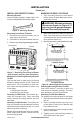
AIR FOR COMBUSTION AND VENTILATION Continued DETERMINING FRESH-AIR FLOW FOR Heater LOCATION Determining if You Have a Confined or Unconfined Space Use this work sheet to determine if you have a confined or unconfined space. Space: Includes the room in which you will install heater plus any adjoining rooms with doorless passageways or ventilation grills between the rooms. 1. Determine the volume of the space (length x width x height). Length x Width x Height =__________cu. ft.
AIR FOR COMBUSTION AND VENTILATION Continued 12" Ventilation Grills into Adjoining Room, Option 1 Ventilation Grills Into Adjoining Room, Option 2 Or Remove Door into Adjoining Room, Option 3 ing and one within 12" (30.5 cm) of the floor. Connect these items directly to the outdoors or spaces open to the outdoors. These spaces include attics and crawl spaces. Follow the National Fuel Gas Code, ANSI Z223.1/NFPA 54, Air for Combustion and Ventilation for required size of ventilation grills or ducts.
INSTALLATION Continued LOCATING HEATER This heater is designed to be mounted on a wall. WARNING: Maintain the minimum clearances shown in Figure 4. If you can, provide greater clearances from floor, ceiling and joining wall. You can locate heater on floor, away from a wall. An optional floor mounting stand is needed. Purchase the floor mounting stand from your dealer. See Accessories, page 27, if stand is not included with your heater.
INSTALLATION Continued INSTALLING HEATER TO WALL Mounting Bracket Locate mounting bracket in heater carton. Remove mounting bracket from heater carton. Figure 6 - Mounting Bracket Removing Front Panel Of Heater 1. Remove the four painted screws, two on each side of front panel. 2. Pull bottom of front panel forward, then out. 3. Remove any remaining packaging materials. 1. Tape mounting bracket to wall where heater will be located. Make sure mounting bracket is level.
INSTALLATION Continued Attaching To Wall Anchor Method For attaching mounting bracket to hollow walls (wall areas between studs) or solid walls (concrete or masonry) 1. Drill holes at marked locations using 5/16" drill bit. For solid walls (concrete or masonry), drill at least 1" (2.5 cm) deep. 2. Fold wall anchor as shown in Figure 9. 3. Insert wall anchor (wings first) into hole. Tap anchor flush to wall. 4. For thin walls [1/2" (1.3 cm) or less], insert red key into wall anchor.
INSTALLATION Continued 3. Align holes in base foot with mounting holes on bottom of cabinet (see Figure 13). 4. Secure base foot to heater using sheet metal screws. 5. Repeat for other side. Wood Screw Base Foot Sheet Metal Screw Figure 13 - Installing Base Feet (actual heater may vary from illustration) Mounting Base Feet to Floor 1. Remove front panel (see Removing Front Panel of Heater, page 9). 2. Position heater with base feet in desired location. Mark holes for drilling. Remove heater with base.
INSTALLATION Continued IMPORTANT: Install an equipment shutoff valve in an accessible location. The equipment shutoff valve is for turning on or shutting off the gas to the appliance. Check your building codes for an special requirements for locating equipment shutoff valve to heater. Apply pipe joint sealant lightly to male NPT threads. This will prevent excess sealant from going into pipe. Excess sealant in pipe could result in clogged heater valves.
INSTALLATION Continued 2. Cap off open end of gas pipe where equipment shutoff valve was connected. 3. Pressurize supply piping system by either opening propane/LP supply tank valve for propane/LP gas or opening main gas valve located on or near gas meter for natural gas or using compressed air. 4. Check all joints of gas supply piping system. Apply a commercial leak detection solution to all joints. Bubbles forming show a leak. 5. Correct all leaks at once. 6.
Operation FOR YOUR SAFETY READ BEFORE LIGHTING WARNING: If you do not follow these instructions exactly, a fire or explosion may result causing property damage, personal injury or loss of life. A. This appliance has a pilot which must be lighted by hand. When lighting the pilot, follow these instructions exactly. B. BEFORE LIGHTING smell all around the appliance area for gas. Be sure to smell next to the floor because some gas is heavier than air and will settle on the floor.
OPERATion Continued 10. To shut off burners only and leave pilot lit, turn control knob clockwise to the PILOT position. Control Knob WARNING: Always operate manual control heaters at the locked positions. Operation between these positions may create a possible health hazard if used in a poorly ventilated room. Read owner’s manual for complete instructions. CAUTION: Do not try to adjust heating levels by using the equipment shutoff valve.
OPERATion Continued Thermostat Control Operation CAUTION: Label all wires prior to disconnection when servicing controls. Wiring errors can cause improper and dangerous operation. The thermostatic control used on these models differs from standard thermostats. Standard thermostats simply turn on and off the burner. The thermostat used on this heater senses the room temperature. At times the room may exceed the set temperature. If so, the burner will shut off.
Inspecting heaters Check pilot flame pattern and burner flame patterns often. PILOT FLAME PATTERN Figure 26 shows a correct pilot flame pattern. Figure 27 shows an incorrect pilot flame pattern. The incorrect pilot flame is not touching the thermocouple. This will cause the thermocouple to cool. When the thermocouple cools, the heater will shut down.
CLEANING AND MAINTENANCE Continued We also recommend that you keep the burner tube and pilot assembly clean and free of dust and dirt. To clean these parts we recommend using compressed air no greater than 30 PSI. Your local computer store, hardware store or home center may carry compressed air in a can. If using compressed air in a can, please follow the directions on the can. If you don’t follow directions on the can, you could damage the pilot assembly. 1. Shut off unit, including pilot.
Troubleshooting WARNING: Turn off and unplug heater and let cool before servicing. Only a qualified service person should service and repair heater. CAUTION: Never use a wire, needle or similar object to clean ODS/pilot. This can damage ODS/pilot unit. Note: All troubleshooting items are listed in order of operation. OBSERVED PROBLEM POSSIBLE CAUSE When ignitor button is 1. Ignitor electrode positioned pressed in, there is no spark wrong at ODS/pilot 2. Ignitor electrode broken 3.
TROUBLESHOOTING Continued OBSERVED PROBLEM POSSIBLE CAUSE REMEDY ODS/pilot lights but flame 1. Control knob not fully 1. Press in control knob fully goes out when control knob pressed in is released 2. Control knob not pressed in 2. After ODS/pilot lights, keep long enough control knob pressed in 30 seconds 3. Equipment shutoff valve not 3. Fully open equipment shutfully open off valve 4. Pilot flame not touching 4.
TROUBLESHOOTING Continued WARNING: If you smell gas Shut off gas supply. Do not try to light any appliance. Do not touch any electrical switch; do not use any phone in your building. Immediately call your gas supplier from a neighbor’s phone. Follow the gas supplier’s instructions. • If you cannot reach your gas supplier, call the fire department. • • • • important: Operating heater where impurities in air exist may create odors.
Parts Cabinet body Models GWRP16C, GWRn18C, GWRP26C, GWRn30C, GWRP16TC, GWRn18TC, GWRP26TC, GWRn30TC, VSHRP16M, VSHRP16T, VSHRN18M, VSHRN18T, VSHRP26M, VSHRP26T, VSHRN30M, and VSHRN30T 7 5 6 17 10 14 15 8 4 See Pages 24 and 25 16 See page 24 2 20 3 13 9 Replacement may vary from grill shown 12 18 11 19 1 Actual part may vary from illustration 22 www.fmiproducts.
Parts KEY NO. 1 2 3 4 5 6 7 9 10 11 12 13 14 15 16 17 18 19 20 PART NO.
Parts Burner Assembly This list contains replaceable parts used in your heater. When ordering parts, follow the instructions listed under Replacement Parts on page 27 of this manual.
Parts Burner Assembly This list contains replaceable parts used in your heater. When ordering parts, follow the instructions listed under Replacement Parts on page 27 of this manual.
Parts Burner Assembly 4 4 KEY NO. PART NO. 5 1 1 5 6 1 2 3 6 4 5 2 3 6 2 120630-02 120630-03 099387-11 104818-03 099218-08 099056-24 099056-25 099056-01 099056-02 DESCRIPTION ODS/Pilot LP ODS/Pilot NG Pilot Tubing Outlet TubingValve to Burner Burner Orifice - Plaque A Orifice - Plaque A Orifice - Plaque B Orifice - Plaque B GW RP1 6TC , VS GW HRP RN1 16T 8TC , VS HRN 18T This list contains replaceable parts used in your heater.
Accessories Purchase these heater accessories from your local dealer. If they can not supply these accessories, either contact your nearest Parts Central or call FMI PRODUCTS, LLC at 1-866-328-4537 for information. You can also write to the address listed on the back page of this manual. Fan kit - pp100 For all models. Provides better heat distribution. Complete installation and operating instructions included. Thermostatically-controlled, blower turns itself on and off as required.
Warranty KEEP THIS WARRANTY Model (located on product or identification tag)______________________________ Serial No. (located on product or identification tag)___________________________ Date Purchased ___________________________ Keep receipt for warranty verification.