
Fireplace Manufacturers Inc Gas Heater User Manual


www.fmiproducts.com
125311-01A16
OPERATION
Continued
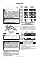
THERMOSTAT CONTROL
OPERATION
The thermostatic control used on these
models differs from standard thermostats.
Standard thermostats simply turn on and off
the burner. The thermostat used on this heater
senses the room temperature. At times the
room may exceed the set temperature. If so,
the burner will shut off. The burner will cycle
back on when room temperature drops below
the set temperature. The control knob can be
set to any comfort level between 1 and 5. All
plaques will turn off and on.
Note: The thermostat sensing bulb mea-
sures the temperature of air near the heater
cabinet. This may not always agree with
room temperature (depending on housing
construction, installation location, room size,
open air temperatures, etc.) Frequent use of
your heater will let you determine your own
comfort levels.
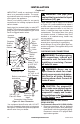
MANUAL LIGHTING
PROCEDURE
1. Remove front panel (see Figure 7, page 9).
2. Follow steps 1 through 5 under Lighting
Instructions, page 14.
3. With control knob pressed in, strike match.
Hold match to pilot until pilot lights.
4. Keep control knob pressed in for 30 sec-
onds after lighting pilot. After 30 seconds,
release control knob. Now follow step 9
under Lighting Instructions, page 14.
5. Replace front panel.
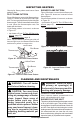
BLOWER
OPERATION
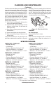
WARNING: Blower acces-
sory must be grounded. Blower
comes with a three-prong,
grounding plug as shown in
Figure 24. The plug is your
protection against electrical
shock. Plug it into a standard,
three-hole, grounded, outlet. If
cord needs replacing, use only a
cord with a three-prong, ground-
ing plug.
CAUTION: Label all wires
prior to disconnection when
servicing controls. Wiring errors
can cause improper and danger-
ous operation.
CAUTION: Do not plug power
cord into electrical outlet until
installation is complete.
Extension Cord
Use extension cord if needed. The cord must
have a three-prong, grounding plug and a
three-hole receptacle. Make sure cord is in
good shape. It must be heavy enough to carry
the current needed. An undersized cord will
cause a drop in line voltage. This will result in
loss of power and overheating. Use a No. 16
AWG cord for lengths less than 50 feet.
CAUTION: Verify proper op-
eration after servicing.
Operating Blower
The blower is connected to a thermostat.
When unit heats up, the blower will operate.
A few minutes after unit cycles off or is turned
off, blower will shut off. Blower will cycle on
and off in this manner. Note: If you have a
heater with a thermostat, the heater and
blower will not turn off and on at exactly the
same time. Blower cycle times will vary with
heat setting selected.
Grounded
Outlet
Figure 24 - Grounding Plug
Thermostat
Sensor
Switch
Green
White
Green
White
110/115
V.A.C.
Blower
Motor
Black
Black
Figure 25 - Wiring Diagram for Blower
Accessory