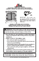
UNVENTED (VENT-FREE) GAS STOVE HEATER OWNER’S OPERATION AND INSTALLATION MANUAL PFS ® US IMPORTANT: This burner system must be installed into approved FMI PRODUCTS, LLC cast iron stove bodies, models CISB, CISNI, CISAW or CISAS only. Models SVYD18NRA and SVYD18PRA Remote-Ready Control Gas Log Heater (Burner System For Cast Iron Stoves) WARNING: If the information in this manual is not followed exactly, a fire or explosion may result causing property damage, personal injury or loss of life.
Table of Contents Safety................................................................... 2 Product Identification............................................ 4 Local Codes......................................................... 5 Product Features.................................................. 5 Air For Combustion And Ventilation...................... 5 Installation............................................................ 8 Operation............................................................
SAFETY Continued Carbon Monoxide Poisoning: Early signs of carbon monoxide poisoning resemble the flu, with headaches, dizziness or nausea. If you have these signs, the heater may not be working properly. Get fresh air at once! Have heater serviced. Some people are more affected by carbon monoxide than others. These include pregnant women, people with heart or lung disease or anemia, those under the influence of alcohol and those at high altitudes.
SAFETY Continued 6. Do not add extra logs or ornaments such as pine cones, vermiculite or rock wool. Using these added items can cause sooting. 7. This log heater is designed to be smokeless. If logs ever appear to smoke, turn off heater and call a qualified service person. Note: During initial operation, slight smoking could occur due to log curing and heater burning manufacturing residues. 8. To prevent the creation of soot, follow the instructions in Cleaning and Maintenance, page 18. 9.
Local Codes Install and use heater with care. Follow all local codes. In the absence of local codes, use the latest edition of The National Fuel Gas Code, ANSI Z223.1/NFPA 54*. *Available from: American National Standards Institute, Inc. 1430 Broadway New York, NY 10018 National Fire Protection Association, Inc. Batterymarch Park Quincy, MA 02269 State of Massachusetts: The installation must be made by a licensed plumber or gas fitter in the Commonwealth of Massachusetts.
AIR FOR COMBUSTION AND VENTILATION Continued Unusually Tight Construction The air that leaks around doors and windows may provide enough fresh air for combustion and ventilation. However, in buildings of unusually tight construction, you must provide additional fresh air. Unusually tight construction is defined as construction where: a.
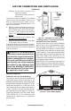
AIR FOR COMBUSTION AND VENTILATION Continued Example: 51,200 Btu/Hr (maximum the space can support) 70,000 Btu/Hr (actual amount of Btu/Hr used) The space in the above example is a confined space because the actual Btu/Hr used is more than the maximum Btu/Hr the space can support. You must provide additional fresh air. Your options are as follows: A. Rework worksheet, adding the space of an adjoining room.
Installation NOTICE: This heater is intended for use as supplemental heat. Use this heater along with your primary heating system. Do not install this heater as your primary heat source. If you have a central heating system, you may run system’s circulating blower while using heater. This will help circulate the heat throughout the house. In the event of a power outage, you can use this heater as your primary heat source. WARNING: A qualified service person must install fireplace. Follow all local codes.
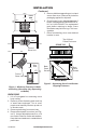
Installation Continued Ceiling 12" Minimum Side Wall 5. Remove bubble-wrapped log set, rod and screen from stove. Remove all protective packaging applied for shipment. 6. Check heater for any shipping damage. If heater is damaged call FMI PRODUCTS, LLC at 1-866-328-4537 for replacement parts before returning to dealer. Some fiber flakes may fall from logs. This is acceptable. 7. Place freestanding stove near desired location in room.
Installation Continued One-Piece Log Set CAUTION: Do not remove the data plates attached to the heater base assembly. The data plates contain important warranty and safety information. WARNING: Failure to position the parts in accordance with these diagrams or failure to use only parts specifically approved with this heater may result in property damage or personal injury. Installing gas log into stove 1. Remove log from carton. 2. Remove all protective packaging applied to log for shipment. 3.
Installation Continued WARNING: Never connect natural gas heater to private (nonutility) gas wells. This gas is commonly known as wellhead gas. Installation Items Needed Before installing heater, make sure you have the items listed below.
Installation Continued CAUTION: Avoid damage to regulator. Hold gas regulator with wrench when connecting it to gas piping and/or fittings. CAUTION: Make sure external regulator has been installed between propane/LP supply and heater. See guidelines under Connecting to Gas Supply, page 10. PROPANE/LP Pressure Testing Gas Supply Piping System Test Pressures In Excess Of 1/2 PSIG (3.5 kPa) NATURAL 1.
Installation Continued Pressure Testing Heater Gas Connections 1. Open equipment shutoff valve (see Figure 11, page 12). 2. Open main gas valve located on or near gas meter for natural gas or open propane/LP supply tank valve. 3. Make sure control knob of heater is in the OFF position. Propane/LP Supply Tank Equipment Shutoff Valve 4. Check all joints from equipment shutoff valve to control valve (see Figure 12 or 13). Apply a noncorrosive leak detection fluid to gas joints. Bubbles forming show a leak.
Operation FOR YOUR SAFETY READ BEFORE LIGHTING LIGHTING INSTRUCTIONS WARNING: If you do not follow these instructions exactly, a fire or explosion may result causing property damage, personal injury or loss of life. NOTICE: During initial operation of new heater, burning logs will give off a paper-burning smell. Open window to vent smell. This will only last a few hours. A. This appliance has a pilot which must be lighted by hand. When lighting the pilot, follow these instructions exactly. B.
Operation Continued person or gas supplier for repairs. Note: If pilot goes out, repeat steps 4 through 8. 9. Slightly push in and turn control knob counterclockwise to the ON position. 10. Wait one minute and switch remote selector switch to the ON position to light burners. Note: AUTO is only functional when using GWMT1 or GWMS2 optional accessories. 11. Set flame adjustment knob to any level between HI and LO. 12.
Operation Continued Flame Adjustment Knob IMPORTANT: Do not leave the selector switch in the REMOTE or ON position when the pilot is not lit. This will drain the battery. PILOT ON Remote Selector Switch in REMOTE Position (Optional Remote Control) O FF IH ON OFF REMOTE LO Control Knob in ON Position Figure 18 - Setting the Remote Selector Switch, Control Knob and Flame Adjustment Knob for Remote Operation Inspecting Burners Check pilot flame pattern and burner flame patterns often.
Cleaning and Maintenance WARNING: Turn off heater and let cool before cleaning. CAUTION: You must keep control areas, burner and circulating air passageways of heater clean. Inspect these areas of heater before each use. Have heater inspected yearly by a qualified service person. Heater may need more frequent cleaning due to excessive lint from carpeting, pet hair, bedding material, etc. WARNING: Failure to keep the primary air opening(s) of the burner(s) clean may result in sooting and property damage. 2.
Troubleshooting WARNING: Turn off heater and let cool before servicing. Only a qualified service person should service and repair heater. CAUTION: Never use a wire, needle or similar object to clean ODS/pilot. This can damage ODS/pilot unit. Note: All troubleshooting items are listed in order of operation. OBSERVED PROBLEM POSSIBLE CAUSE REMEDY When ignitor button is pressed, there is no spark at ODS/pilot 1. Ignitor electrode not connected to ignitor cable 2. Ignitor cable pinched or wet 1.
Troubleshooting OBSERVED PROBLEM Burner does not light after ODS/pilot is lit Continued POSSIBLE CAUSE 1. Burner orifice clogged 2. Inlet gas pressure is too low 3. Thermopile leads disconnected or improperly connected 4. Burners will not come on in remote position Delayed ignition burner 1. Manifold pressure is too low 2. Burner orifice clogged Burner backfiring during combustion 1. Burner orifice is clogged or damaged 2. Damaged burner 3.
Troubleshooting Continued WARNING: If you smell gas • Shut off gas supply. • Do not try to light any appliance. • Do not touch any electrical switch; do not use any phone in your building. • Immediately call your gas supplier from a neighbor’s phone. Follow the gas supplier’s instructions. • If you cannot reach your gas supplier, call the fire department. IMPORTANT: Operating fireplace where impurities in air exist may create odors.
Specifications SVYD18PRA • Rating: 21,000/31,000 Btu/hr (Variable) • Gas Type: Propane/LP • Ignition: Piezo • Pressure Manifold: 8" W.C. • Inlet Gas Pressure (in. of water): Maximum - 14" W.C., Minimum - 11" W.C. • Shipping Weight: 28 lbs. SVYD18NRA • Rating: 24,000/35,000 Btu/hr (Variable) • Gas Type: Natural • Ignition: Piezo • Pressure Manifold: 3.5" WC • Inlet Gas Pressure (in. of water): Maximum - 10.5" W.C., Minimum - 5" W.C. • Shipping Weight: 28 lbs.
Parts Models SVYD18PRA and svyd18nrA 1 2 21 6 3 7 4 8 5 21 9 22 11 10 12 23 13 15 20 14 17 24 16 17 18 22 12 19 www.fmiproducts.
Parts 1 2 3 4 5 6 7 8 9 10 11 12 13 14 15 16 17 18 19 20 21 22 23 24 DESCRIPTION 104026-01 103778-01 103779-01 098249-01 104423-02 104423-01 098264-02 111124-01 099056-19 099056-26 102980-01 099387-13 099387-15 103781-02 103781-01 103345-02 M11084-38 ** 098271-10 102445-01 103587-02 098304-01 103784-04 103784-03 M12461-26 100609-01 099918-02 103284-02 099998-01 Stove Log ODS Pilot ODS Pilot ODS Nut Burner Outlet Tube Burner Outlet Tube Male Connector Burner Retainer Spring Burner Orifice Injector Burner
Accessories Purchase these accessories from your local dealer. If they can not supply these accessories call FMI PRODUCTS, LLC at 1-866-328-4537 for information. You can also write to the address listed on the back page of this manual. WALL-MOUNT THERMOSTAT SWITCH - GWMT1 For remote-ready models. The desired comfort setting can be selected on the wall thermostat and the log heater will automatically cycle from pilot to the heat setting selected. WALL-MOUNT ON/OFF SWITCH GWMS2 For remote-ready models.
NOTES _____________________________________________________ ______________________________________________________ ______________________________________________________ ______________________________________________________ ______________________________________________________ ______________________________________________________ ______________________________________________________ ______________________________________________________ ______________________________________________________ ___________
NOTES _____________________________________________________ ______________________________________________________ ______________________________________________________ ______________________________________________________ ______________________________________________________ ______________________________________________________ ______________________________________________________ ______________________________________________________ ______________________________________________________ ___________
NOTES _____________________________________________________ ______________________________________________________ ______________________________________________________ ______________________________________________________ ______________________________________________________ ______________________________________________________ ______________________________________________________ ______________________________________________________ ______________________________________________________ ___________
Warranty KEEP THIS WARRANTY Model (located on product or identification tag)______________________________ Serial No. (located on product or identification tag)___________________________ Date Purchased ___________________________ Keep receipt for warranty verification.