Residential and Outdoor Wood burning Fireplace OWNER’S OPERATION AND INSTALLATION MANUAL PFS C ® US ICC-ES #ESR-2542 Models (V)S36 Series SAVE THIS BOOK This book is valuable. In addition to instructing you on how to install and maintain your appliance, it also contains information that will enable you to obtain replacement parts or accessory items when needed. Keep it with your other important papers.
Table of Contents Safety................................................................... 2 Specifications....................................................... 3 Fireplace Installation............................................ 4 Venting Installation............................................... 6 Optional Gas Line Installation.............................11 Operation and Maintenance Guidelines............. 12 Parts...................................................................
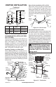
Specifications ELECTRICAL OUTLET 1" AIRSPACE TO COMBUSTIBLE MATERIAL 0" TO TOP SPACERS RIGHT SIDE NO COMBUSTIBLE MATERIAL ON FACE GAS LINE KNOCK OUTS 2.5" 8.125" 7.092" 8.717" 11.217" AIR KIT KNOCK OUT LEFT SIDE GAS LINE KNOCK OUTS COMBUSTIBLE WALL BOARD 3/4" AIR SPACE BACK AND SIDES 10.435" NOT LESS THAN 12" TO PERPENDICULAR SIDEWALL OUTSIDE AIR (LEFT SIDE ONLY) 2.5" 8.125" 8.717" 14.437" HEARTH EXTENSION 52" X 16" 8" EACH SIDE 0" TO BOTTOM 22" 29" 14.25" 21 12.5" 32.5" 0.
Fireplace Installation selecting location To determine the safest and most efficient location for the fireplace, you must take into consideration the following guidelines: 1. The location must allow for proper clearances (see Figures 1 and 2). 2. Consider a location where the fireplace will not be affected by drafts, air conditioning ducts, windows or doors. 3. A location that avoids the cutting of joists or roof rafters will make installation easier. 4.
Fireplace Installation Continued Drain Pan (DP36) For outdoor installations, the fireplace enclosure must allow for adequate drainage and fresh air ventilation. It is recommended that a sealed, corrosion resistant catch pan with provision for drainage be installed under the fireplace within the fireplace enclosure (see Accessories on page 16). Hearth Extension WARNING: Hearth extension is to be installed only as shown in Figure 3. Mantels A mantel may be installed if desired (see Figure 4).
Venting Installation Optional Outside air Kit (Model ak4/ak4f) The installation of an outside air kit should be performed during the rough framing of the fireplace due to the nature of it's location. Outside combustion air is accessed through a vented crawl space (AK4F) or through a sidewall (AK4). See Figure 22 on page 13 for instruction of operating air kit. CAUTION: Combustion air inlet ducts shall not terminate in attic space.
Venting Installation Continued When connecting chimney directly to the fireplace, the inner flue pipe section must be installed first with the lanced side up. The outer pipe section can then be installed over the flue pipe section with the hemmed end up. Press down on each pipe section until the lances securely engage the hem on the fireplace starter. The wire will assure the proper spacing between the inner and outer pipe sections.
Venting Installation Continued See Detail A 2" Min. Existing Ceiling Frame Firestop Spacer Straps Straps Detail B Angle Firestop Straps See Detail B Screws or Staples (Min. of 8) Figure 10 - Firestop Spacer with Living Space Above Ceiling Firestop Spacer Straps Screws or Staples (Min.
Venting Installation Continued Minimum Measurements 14 3/8" (36.5 cm) 30" (76.2 cm) 1" (2.5 cm) 1" (2.5 cm) 1" (2.5 cm) Storm Collar Installation (SC1 or SC2) Place storm collar over pipe and slide down until it is snug against the open edge of the flashing (see Figure 14). Use SC1 for all round terminations and SC2 for all terminations with slip sections. Apply waterproof caulk around the perimeter of the collar to provide a proper seal.
Venting Installation Continued Terminations with 16" slip pipe sections are available. The RTT-8DM and RTTL-8DM are approved for flashing installations. When needed, these adjustable terminations may be used in combination with the pipe assembly to achieve the correct chimney height. Note: In the rare instance there is a problem with the side driven rain or wind or the chimney is not drafting properly, an ADS-8DM (Anti-Draft Shield) can be used with round terminations.
Venting Installation Continued EFFECTIVE HEIGHT EFFECTIVE HEIGHT OF TERMINATION CAP OF TERMINATION CAP MIN. HEIGHT OF 22 FT. (WITH 2 ELBOW SETS) MAX. HEIGHT OF 50 FT. MAX. HEIGHT 50 FT. (ANY SYSTEM) EFFECTIVE HEIGHT EFFECTIVE HEIGHT OF TERMINATION CAP OF TERMINATION CAP 14.5 FT. MINIMUM HEIGHT 14.5 FT. MINIMUM HEIGHT UP TO 6FT. MAX. UP TO 6FT. MAX.
Optional Gas Line Installation Continued CAUTION: All gas piping and connections must be tested for leaks after the installation is completed. After ensuring that the gas valve is on, apply soap and water solution to all connections and joints. Bubbles forming show a leak. Correct all leaks at once. DO NOT USE AN OPEN FLAME FOR LEAK TESTING AND DO NOT OPERATE ANY APPLIANCE IF A LEAK IS DETECTED. LEAK TESTING SHOULD BE DONE BY A QUALIFIED SERVICE PERSON.
Operation and Maintenance Guidelines Continued The following tips should be followed to assure that both the fireplace and the glass door retain their beauty and function properly. Both the flue damper and the glass doors must be fully opened before starting the fire. This will provide sufficient combustion air and maintain safe temperatures in the firebox. IMPORTANT: The glass must be allowed to warm slowly and evenly.
Parts Wood burning Fireplace MODELS S36, S36H, S36R, S36RH, S36-LS, VS36, VS36H, vs36r AND vs36rh 35 29 2 1 21 5 8 17 15 28 20 30 25 9 11 19 18 37/38 7 12 3 34 4 24 36 31 10 32 6 26 33 22 16 13 27 14 16 23 27 14 www.fmiproducts.
PARTS Wood burning Fireplace MODELS S36, S36H, S36R, S36RH, S36-LS, VS36, VS36H, vs36r and vs36rh This list contains replaceable parts used in your fireplace. KEY NO. 1 2 3 4 5 6 7 8 9 10 11 12 13 14 15 16 17 18 19 20 21 22 23 24 25 26 27 28 29 30 31 32 33 34 35 36 37 38 PART NO.
PARTS Wood burning Fireplace MODELS S36, S36H, S36R, S36RH, S36-LS, VS36, VS36H, vs36r and vs36rh Right Side Rear Bottom Front Bottom 16 DESCRIPTION Left Refractory, Textured White Brick Left Refractory, Textured White Herringbone Left Refractory, Textured Red Brick Left Refractory, Textured Red Herringbone Left Refractory, Smooth White Brick Left Refractory, Smooth White Herringbone Right Refractory, Textured White Brick Right Refractory, Textured White Herringbone Right Refractory, Textured Red Brick
Technical Service You may have further questions about installation, operation, or troubleshooting. If so, contact FMI PRODUCTS, LLC at 1-866-328-4537. When calling please have your model and serial numbers of your heater ready. You can also visit FMI PRODUCTS, LLC’s web site at www.fmiproducts.com.
Accessories Continued Round Top Terminations RT-8DM, RTL-8DM RounD Top Terminations with Slip Section Outside Air Kit for Side Wall Installation - AK4 RTT-8DM, RTTL-8DM RounD Top Terminations with LOUVERS RTL-8DM Outside Air Kit for Floor Installation - AK4F Storm Collar SC1-1 For RT-8DM and RTL-8DM SC2-1 For RTT-8DM and RTTL-8DM Square Chase-Top Termination ET-8DM, ETO-8DM Econo-Top Termination with Slip Section ETL-8DM, ETLO-8DM 18 www.fmiproducts.
NOTES _____________________________________________________ ______________________________________________________ ______________________________________________________ ______________________________________________________ ______________________________________________________ ______________________________________________________ ______________________________________________________ ______________________________________________________ ______________________________________________________ ___________
2701 S. Harbor Blvd. Santa Ana, CA 92704 1-866-328-4537 www.fmiproducts.com 111026-01 Rev.