
Fireplace Manufacturers Inc Electric Heater User Manual


www.fmiproducts.com
108662-01L 15
INSTALLATION
Continued
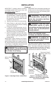
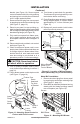
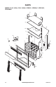
bracket (see Figure 14). Secure speed
control to bracket with lock nut by pushing
and turning lock nut with pliers clockwise
until it is tight against bracket.
7. Remove knockout plug from louver panel
by pressing top and bottom retaining clips
(see Figure 11, page 13).
8. Place louver panel, louvers pointing up,
back into framed opening. Align control shaft
with rectangular opening by sliding control
bracket along ange (see Figure 14).
9. Fully seat louver panel into frame open-
ing by gently pressing along ends until
all dimpled retainers have snapped in
place.
10. Place control knob, provided, onto control
shaft (see Figure 14).
11. Check to make sure power cord is com-
pletely clear of blower wheel and there are
no foreign objects in blower wheel. Also,
double check all wire leads and make
sure wire routing is not pinched or in a
precarious position. Correct accordingly.
-
12. Turn on power to duplex outlet if previ-
ously turned off per warning in column 1,
page 14.
13. Plug in blower power cord to duplex outlet
(see Figure 12, page 14).
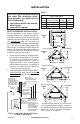
Figure 14 - Attaching Speed Control to
Firebox with Panel Louvers
Control
Shaft
Control
Knob
Lock Nut
Speed
Control
Bracket
Lower
Louver
Firebox Face
Hearth
Pan
Flange
Screw
Head and
Top Hole
on Bracket
Lower
Flange
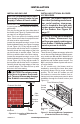
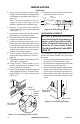
Figure 15 - Location of Wiring Diagram
Decal (Model May Vary From Illustration)
Wiring Diagram
Decal 12" in
Front of Blower
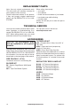
Red
V a riable
Fan Switch
Fan Switch
(N.O.)
Green
White
On
1 1 0/115
V . A.C.
Blower
Motor
Black
Off
1
2
Black
Blue
(BKT Model
Only)
14. Turn blower on and check for operation.
Turn blower off by turning knob fully coun-
terclockwise before continuing.
15. Peel off backing paper and stick supplied
wiring diagram decal on rebox bottom
approximately 12" in from of blower (see
Figure 15).
16. Replace all panels and/or brick bottom
panel if previously removed.
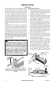
Model BK3 Installation
1. Remove knockout plug from louver panel
by pressing top and bottom retaining clips
(see Figure 11, page 13).
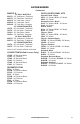
2. Place BK3 fan assembly between two leg
stands with fan blades pointing toward
rear of replace (see Figure 16).
Figure 16 - Mounting BK3 Blower
Screws
BK3 Blower
Leg
Stands