B-VENT DECORATIVE ELECTRONIC IGNITION GAS FIREPLACE OWNER’S OPERATION AND INSTALLATION MANUAL PFS C ® US Natural Gas models m36e(b,h), m42e(b,h), VM36E(B,h) and vm42E(b,h) PROPANE/LP Gas models m36eP(b,h), m42eP(b,h), VM36EP(B,h) and vm42EP(b,h) WARNING: If the information in these instructions is not followed exactly, a fire or explosion may result causing property damage, personal injury or death.
WARNING: Improper installation, adjustment, alteration, service or maintenance can cause injury or property damage. Refer to this manual for correct installation and operational procedures. For assistance or additional information consult a qualified installer, service agency or the gas supplier. NOT FOR USE WITH SOLID FUEL CHECK LOCAL CODES PRIOR TO INSTALLATION SAVE THIS BOOK This book is valuable.
Safety WARNING: This product contains and/or generates chemicals known to the State of California to cause cancer or birth defects or other reproductive harm. IMPORTANT: Read this owner’s manual carefully and completely before trying to assemble, operate or service this fireplace. Improper use of this fireplace can cause serious injury or death from burns, fire, explosions, electrical shock and carbon monoxide poisoning.
Safety Continued 11. Keep the area around your fireplace clear of combustible materials, gasoline and other flammable vapor and liquids. Do not run fireplace where these are used or stored. Do not place items such as clothing or decorations on or around fireplace. 12. Do not use this fireplace to cook food or burn paper or other objects. 13. Do not use any solid fuels (wood, coal, paper, cardboard, etc.) in this fireplace. Use only the gas type indicated on fireplace nameplate. 14.
Introduction Continued The installation must conform with local codes or, in the absence of local codes, with the current National Fuel Gas Code, ANSI Z223.1/ NFPA 54. This appliance complies with ANSI Z21.50/CSA 2.22. WARNING: Installation of this appliance should be done by a qualified service person well trained in the installation of such appliances. You will also need a building permit from your local Building and Safety Commissioner before installing this appliance; otherwise your insurance co.
Product Specifications GAS RATING - NATURAL M36E(B,H), VM36E(B,H) M42E(B,H), VM42E(B,H) Max. Input Rating: 40,000 Btu/Hr 45,000 Btu/Hr Manifold Pressure: 3.5" WC (.87 kPa) 3.5" WC (.87 kPa) Minimum Supply Pressure: 4.5" WC (1.12 kPa) 4.5" WC (1.12 kPa) Maximum Supply Pressure: 10.5" WC (2.66 kPa) 10.5" WC (2.66 kPa) Orifice Size: # 30 # 29 GAS RATING - PROPANE/LP M36P(B,H), VM36P(B,H) M42P(B,H), VM42P(B,H) Max. Input Rating: 40,000 Btu/Hr 45,000 Btu/Hr Manifold Pressure: 10" WC (2.49 kPa) 10" WC (2.
PreInstallation Preparation CLEARANCES Minimum clearances to combustibles are: Back and Sides of Outer Surround 0" min. Drywall to Sides of Front Face (Nailing Flanges) 0" min. “B” Vent Surfaces 1" min. Ceiling to Opening 42" min. Floor 0" min. Perpendicular Wall See Figure 6 CAUTION: Do not block required air spaces with insulation or any other material. Do not obstruct effective opening of appliance with any type of facing material.
PreInstallation Preparation Continued FRAMING 1. Frame appliance enclosure as illustrated in Figures 7 and 8. Note: If a wall covering is used to line enclosure, then all measurements must be from surface of covering. 2. Place appliance into framing and secure. Note: If appliance is to be raised above floor level, a platform must be built to support appliance. 3. Install supply line to appliance using a 1/2" NPT black iron gas line terminating 2 5/16" above bottom of appliance.
PreInstallation Preparation Continued Installing Transition Pipe and Starter Collar The transition pipe and starter collar shown in Figure 9 are supplied with fireplace, unattached and ready for installation. Remove starter collar and set aside. Slide transition pipe over vent collar and attach with a minimum of three screws. Replace starter collar over transition pipe and attach using four screws located on leg stands (five used on model M42E).
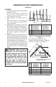
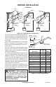
Venting INSTALLATION Continued Listed Vent Cap Listed Vent Cap Listed Vent Cap Maintain Listed Clearance Maintain Listed Clearance Support Each Lateral At Least Every 6 Feet 60° 8' Position 12' Min. Firestop 6' Maintain Listed Clearance EXAMPLE 1 Position Firestop 45° Maintain Listed Clearance 45° 12' Min. Position Firestop Maintain Listed Clearance 45° 10' 12' Min.
Venting INSTALLATION Continued CHECKING FOR PROPER VENTING After completing and checking electrical, gas and vent connections, follow the lighting instructions and allow the main burner to run for approximately 5 minutes. Hold a lighted match or cigarette near the top edge of fireplace opening and play it along entire length of opening (see Figure 12). Proper venting should tend to draw the flame or smoke into the appliance.
Installation Continued 3. Activate remote handset battery by removing insulating tab on back of handset (see Figure 15). Battery is included preinstalled. 4. Once the battery is activated unit is ready to use. 5. Replace front refractory access panel. Battery Cover 12 Volt Battery Back of Handset FMI PRODUCTS, LLC recommends that a black iron gas line be routed from the gas source, through a sediment trap (shown in Figure 18) and into appliance.
Installation Continued CAUTION: Compounds used on threaded joints of gas piping shall be resistant to the action of Liquefied Petroleum (LP or propane) and should be applied lightly to ensure excess sealant does not enter the gas line. WARNING: All gas piping and connections must be tested for leaks after the installation is completed. After ensuring that gas valve is on, apply a commercial leak detection solution to all connections and joints. If bubbles appear, leaks can be detected and corrected.
Installation Continued Grate 0.5" Pan and Ember Material 0.5" Burner Pan NOTICE: Do not put lava rock inside the burner pan or around the air mixer fitting. Placing lava rock inside the burner pan or blocking the openings of the propane/LP air mixer could cause performance problems. Log 4 Figure 22 - Pan and Ember Material Clearances LOG PLACEMENT For Models M36E, M36EP, VME36 and VM36EP 1. Place small front right log (log 1) on right front of grate as shown in Figure 23. 2.
Installation Continued LOG PLACEMENT For Models M42E, M42EP, VME42 and VM42EP 1. Place large back log (log 1) onto grate making sure notches rest over grate (see Figure 27). 2. Insert lower end of log 2A between first two grate fingers and position upper end into notch on front of log 1. See Figure 27. Place log 2B on front right side of grate as shown in Figure 27. 3. Place log 3 into notch on top left of log 1, resting lower end on left two grate fingers (see Figure 28). 4.
Installation Continued COMBUSTION AIR KIT MODEL AK4 (OPTIONAL) The outside air kit may be installed on the left side of fireplace only. The vent can be installed through any outside wall a minimum of three feet below fireplace termination cap. The handle to operate damper door for outside air inlet will be located inside left “screen pocket” of firebox (see Figure 31). Pull handle to open or push to close. CAUTION: Air inlet ducts are not to terminate in attic space.
Installation Continued 6. Repeat process for opposite door assembly. 7. To adjust doors, slide them partially open. Using a screwdriver, loosen hold-down screws in the spring clip (see Figure 34) and pivot plate. 8. Close both doors until evenly joined at the middle and note gap at outer edges of face. 9. Reopen one door at a time and retighten upper and lower hold-down screws. 10. Repeat process until both doors are evenly joined, spaced and working freely.
Operation FOR YOUR SAFETY READ BEFORE LIGHTING WARNING: If you do not follow these instructions exactly, a fire or explosion may result causing property damage, personal injury or loss of life. A. This appliance has a pilot which must be lighted by hand. When lighting the pilot, follow these instructions exactly. B. BEFORE LIGHTING smell all around the appliance area for gas. Be sure to smell next to the floor because some gas is heavier than air and will settle on the floor.
Operation Continued TO TURN OFF GAS TO APPLIANCE 1. Turn off wall switch. 2. Turn off all electric power to appliance if service is to be performed. 3. Fully open glass doors if installed. 4. Remove front hearth brick and control access panel. 5. Turn gas control knob clockwise to OFF. Do not force. 6. Replace front refractory brick access panel. 7. Fully close glass doors if installed. 1. Turn equipment shutoff valve to ON position.
Cleaning and Maintenance WARNING: Installation and repair should be done by a qualified service person. The appliance should be inspected before each use and at least annually by a qualified service person. More frequent cleaning may be required due to excessive lint from carpeting, bedding material, pet hair, etc. It is imperative that the control compartments, burners and circulating air system be kept clean. WARNING: The logs can be hot. Handle only when cool.
Wiring Diagram Pilot Burner Pilot Gas Line OFF WALL SWITCH (NOT SUPPLIED) ON INCOMING MAIN GAS SUPPLY BLACK IGN WHITE GND TR PV/MV BLACK WHITE GREEN PV EV1 GREEN Robertshaw MODEL SP745 IGNITION CONTROL VENT SAFETY SHUTOFF SWITCH MANUAL DAMPER SWITCH INCOMING 120V AC (FUSE BOX OR BREAKER) TH MV ELECTRICAL RATING: 120v, 60Hz, 0.
Troubleshooting Note: Before troubleshooting the system, make sure the gas shutoff valve is ON. The two most common causes of a malfunctioning gas appliance are: 1. Loose wiring connections 2. Construction debris clogging the pilot and/or gas control valve filter OBSERVED PROBLEM POSSIBLE CAUSE REMEDY Ignitor will not spark or pilot 1. No gas supply or shutoff 1. Check to see if you have gas will not light valve is OFF supply and that equipment shutoff valve is opened 2. Air in gas line 2.
TROUBLESHOOTING Continued WARNING: If you smell gas • Shut off gas supply. • Do not try to light any appliance. • Do not touch any electrical switch; do not use any phone in your building. • Immediately call your gas supplier from a neighbor’s phone. Follow the gas supplier’s instructions. • If you cannot reach your gas supplier, call the fire department. IMPORTANT: Operating fireplace where impurities in air exist may create odors.
Parts Models M36E(B,H), M36EP(B,H), M42E(B,H), M42EP(B,H), VM36E(B,H), VM36EP(B,H), VM42E(B,H) and VM42EP(B,H) 51 50 21 28 32 26 31 27 37 36 38 LP 35 34 50 10 11 30 33 6 29 25 34 35 NG 25 1 24 11 22 49 52 43 14 12 62 52 15 48 16 7 13 55 41 46 9 42 17 9 8 19 40 20 2 39 4 23 5 45 47 18 44 3 7 47 24 www.fmiproducts.
Parts This list contains replaceable parts used in your heater. When ordering parts, follow the instructions listed under Replacement Parts on page 20 of this manual. KEY NO.
Parts This list contains replaceable parts used in your heater. When ordering parts, follow the instructions listed under Replacement Parts on page 20 of this manual. 14 12 16 13 15 KEY M36(B,H) NO.
Parts Logsets for models M36(B,H), M36P(B,H), VM36(B,H) and VM36P(B,H) 5 4 6 3 5 4 2 3 1 KEY NO. PART NO. DESCRIPTION 1 2 3 4 5 6 Log Set Right Front 9" Split Log Rear Log Top Right Log - 11 3/4" Top Right Log - 16" Top Left Log - 13 1/2" Y-Log Top Left Log - 11" 107999-01 108724-01 901098-01 108720-01 108721-01 108722-01 108723-01 QTY. 1 1 1 1 1 1 1 2A 2B 108796-01UT www.fmiproducts.
5 Parts 4 for Logsets models M42(B,H), M42P(B,H), VM42(B,H) and VM42P(B,H) 3 5 4 3 1 6 1 2A 2B KEY NO. PART NO. 1 2A 2B 3 4 5 6 28 107999-02 901098-02 108723-01 108839-01 108722-01 108838-01 108721-01 108720-01 DESCRIPTION Log Set Rear Log Left Front Log - 11" Right Front Log - 15 3/4" Round Top Left Log - 13 1/2" Y-Log Inside Top Left Log - 15 3/4" Split Inside Top Right Log - 16" Top Right Log - 11 3/4" www.fmiproducts.com QTY.
Accessories Notice: All accessories may not be available for all fireplace models. Purchase these accessories from your local dealer. If they can not supply these accessories call FMI PRODUCTS, LLC at 1-866-328-4537 for information. You can also write to the address listed on the back page of this manual. Blower Kit Air kit - AK4 Optional kit helps offset the negative pressure often existing in today's tightly constructed homes.
NOTES _____________________________________________________ ______________________________________________________ ______________________________________________________ ______________________________________________________ ______________________________________________________ ______________________________________________________ ______________________________________________________ ______________________________________________________ ______________________________________________________ ___________
NOTES _____________________________________________________ ______________________________________________________ ______________________________________________________ ______________________________________________________ ______________________________________________________ ______________________________________________________ ______________________________________________________ ______________________________________________________ ______________________________________________________ ___________
Warranty KEEP THIS WARRANTY Model (located on product or identification tag)______________________________ Serial No. (located on product or identification tag)___________________________ Date Purchased ___________________________ Keep receipt for warranty verification.