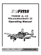
70MM A-10 Thunderbolt II REALISTIC RETRACT & FLAPS INSTALLED RIGID STRONG DURABLE EPO STABLE SMOOTH FLYING PERFORMANCE FMSMODEL.
WARNING: Read the ENTIRE instruction manual to become familiar with the features of the product before operating. Failure to operate the product correctly can result in damage to the product,personal property and cause serious injury. This is a sophisticated hobby product and NOT a toy. It must be operated with caution and common sense and failure to do so could result in injury or damage to the product or other property. This product is not intended for use by children without direct adult supervision.
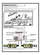
Table of Contents Introductions ··························································································································3 Contents of Kit ························································································································4 Model Assembly ······················································································································5 Battery and radio installation ···················································
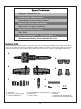
Wingspan: 1500mm (59.1in) Overall Length: 1368mm (53.9in) Flying Weight: Around 4100g (144.6oz) Motor Size: Brushless 2860-KV1850*2 Wing Load: 113.2 g/dm² (0.26oz/in²) Wing Area: 36.2 dm² (561 sq.in) ESC: 70A*2 Servo: 9g metal digital * 5 17g metal digital * 4 Recommended Battery: 22.2V 5000mAh 45C Li-Po Contents of Kit Before assembly, please inspect the contents of the kit. The photo below details the contents of the kit and labels.
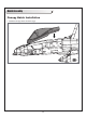
Model Assembly Canopy Hatch Installation 1. Install the canopy hatch as shown (fig1).
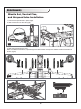
Model Assembly Main Wing Installation 1.Slide the wing tube into the fuselage (fig2). 2. Install the left and right wing over the wing tube and into the wing slot of the fuselage. Notice: The connectors on both sides should be attached precisely and firmly. fig2 3. Secure the left and right wings to the fuselage using the 4 screws included (fig3). HKM3.
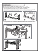
Model Assembly Horizontal and Vertical Stabilizer Installation 1. Connect the rudder servo connectors to the servo extensions in the elevator . 2. Carefully slide the two vertical tail pieces (left and right) into the slots of horizontal tail as shown (fig4). 3. Secure the two vertical tail pieces (left and right) in place using the 4 screws included (fig5). HKM3.0*16 fig4 fig5 4. Connect the elevator servo connectors and rudder servo connectors to the servo extensions in the fuselage. 5.
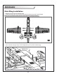
Model Assembly Missile Set, Ventral Fins, and Airspeed tube Installation 1. Screw the air speed tube in place (fig8). 2. Slide ventral fins into the rails (fig9). fig8 fig9 3. Slide the missiles into the rails. Note: to fit different anhedrals, separate right and left missiles are required. Please install the missiles as shown. (fig10).
Battery and radio installation 1. Apply the hook strap to your battery as shown. 2. Carefully lift the canopy hatch to remove. 3. Install the full charged battery in the battery compartment with the power supply cable toward the rear end of the plane. Note: you may need to relocate the battery position to achieve the correct CG for your model.
Get your model ready to fly Important ESC and model information 1. The ESC included with the model has a safe start. If the motor battery is connected to the ESC and the throttle stick is not in the low throttle or off position, the motor will not start until the throttle stick is moved to the low throttle or off position. Once the throttle stick is moved to the low throttle or off position, the motor will emit a series of beeps.
Check the control throws The suggested control throw setting for FMS MODEL are as follows (dual rate setting): 20 23 20 15 18 15 Tips: On first flight, fly the model in low rate. The first time you use high rates, be sure to fly at low to medium speeds. High rate, as listed, is only for EXTREME maneuvering.
Control Horn and Servo Arm Settings The table shows the factory settings for the control horns and servo arms. Fly the aircraft at the factory settings before making changes. After flying, you may choose to adjust the linkage positions for the desired control response.
Check the C.G. (Center of Gravity) When balancing your model, adjust the motor battery as necessary so the model is level or slightly nose down. This is the correct balance point for your model. After the first flights, the CG position can be adjusted for your personal preference. 1. The recommended Center of Gravity (CG) location for your model is (80-85mm) forward from the leading edge of the main wing (as shown) with the battery pack installed. Mark the location of the CG on top of the wing. 2.
Before flying the model Find a suitable flying site Find a flying site clear of buildings, trees, power lines and other obstructions. Until you know how much area will be required and have mastered flying your plane in confined spaces, choose a site which is at least the size of two to three football fields - a flying field specifically for R/C planes is best. Never fly near people especially children, who can wander unpredictably.
Flying Course Take off While applying power, slowly steer to keep the model straight. The model should accelerate quickly. As the model gains flight speed you will want to climb at a steady and even rate. It will climb out at a nice angle of attack (AOA). Flying Always choose a wide-open space for flying your plane. It is ideal for you to fly at a sanctioned flying field. If you are not flying at an approved site always avoid flying near houses, trees, wires and buildings.
Troubleshooting 16
Spare parts list content FMSPV101 Fuselage FMSPV102 Main Wing Set FMSPV103 Vertical Stabilizer FMSPV104 Horizontal Stabilizer FMSPV105 Cockpit FMSPV106 Bomb and Missile Set FMSPV107 Twin Engine Compartment FMSPV108 Foam part (Laser racker) FMSPV109 Foam part (fin) FMSPV110 Scale Plastic Parts Set FMSPV111 Control Horns FMSPV112 Linkage Rod FMSPV113 Screw Set FMSPV114 LED FMSPV115 Front Landing Gear Set FMSPV116 Main Landing Gear Set FMSPV117 Front Landing Gear System FMSPV118 Main Landing Gear System FMSPV1
ESC instruction 18