Perfect Appearance Excellent Performance EASY TRAINER 1280 OPERATING MANUAL Please visitor our Facebook fan page and our homepage for updated product information Mh eh hits few face binary ean os new enamel cam
WARNING A WARNING: Read the ENTIRE instruction manual to become familiar with the features of the product before operating. Failure lo operate the product correctly can resell in damage lo the product, personal propellant cause serious injury. This is a sophisticated hobby product and NOT a toy. must be operated with caution and common sense and requires some basic mechanical ability.
Table of contents J BitTorrent. cheerlessness 1 The spare pairs Fxg oo ROR 2 Spare parts Five CORPORAL The illustration of the spare parts cocci: 4 Kir inspection ee. 5 Assemble the plane...
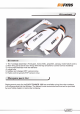
Kit contents ) Kit contents 1: The fuselage assembly Front gear, moor, ESC, propeller, canopy, motor hatch cover) 2. Mainwing set (Asset of main wings with the flap and aileron control servos installed) 3. Horizontal Stabilizer with the elevator 4: wings tube 8. battery and charger (RTE version only) 6. Radio control system (RTE version only) The spare pairs list J Replacement parts for the EASY TRAINER 1280 are available using the order numbers in the Spare parts list that follows.
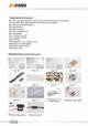
Spare parts list content S50 101 Fuselage (With the motor board and extension wire installed) S80 102 Main wing set {With all the plastic part installed) 80 103 Horizontal Stabilizer 50 104 Canopy 80 105 Propeller S80 107 Linkage Rods 50 112 Sticker 80 113 Moor mount SQ 114 Motor Board 50 115 Pipe 4V 1300mah 200 EM-Molor-3128 Kv2650 FM S-Servo-8-positive F ME-EBC-20A The illustration of the spare parts EMS-Battler-7 4V S-115 1300mah 20C FEM-Motor-3128 Kraal F MS-ESC-20A
Kit inspection J Before starting to build, inspect the parts lo make sure they areacceplablequality Han pairs are missing renovator in good shape or acceptable quality, or you need assistance with setup and assembly please feel free to contact ROC TEAM Please write down the name of the parts when you are reporting defective or missing of them. ROC TEAM Product Support ADDRESS: 3/F, Building B, 3rd Industry Zone, Mating, Tangshan Town, Guangdong City PRC Ph: 0086.769.
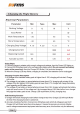
Charging the Flight Battery | Electrical Parameters Parameter Min Type Max Unit Waring Foliage Input Power 15 w Work Temperature ~=20 45 °C Store Temperature -20 65 TC Charging Stop Voltage 4.18 4.20 4.21 V Charging Current 10040 mA Balancing Current 150 200 mA Activate Current 80 120 mA Using Steps: 1. Connect charger lo adapter with enough voltage and wastage, then the Power LED lights on. 2.
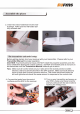
Assemble the plane J The control horns installation 1. stall the horizontal stabilizer home, fit the horn into the per-notched slot on tha down side ol the horizontal stabilizer that contain the servos. ik Install the horizontal stabilizer 1. Applique on the combined side of sees. the elevator. 2. Page the back plate gn the opposite side with the two small protrude collars filled into the control surface. 3. Secure the control horn from the horn mounting side using the provided screws.
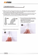
Assemble the plane J 2. insertions side of stabilizer into the rear fuselage, make sure two half stabilizer fully connect well The transmitter and model setup Before getting started, bind your receiver with your transmitter. Please refectory Transmitter Manual nonproliferation: CAUTION: To prevent personal injury, DO NOT install the propeller assembly onto the motor shaft while testing the control surfaces.
Assemble the plane J J. Make swe all servomechanism fully vertical li nol stadium thermostat by using the nim function on your radio: Note For computerized transmitters, use the servomechanism sub-trim feature to make each servo arm fully vertical. 4. The standard hole settings for linkage connections are shown by the black arrows in the the diagram below, You can move the linkage to different hole positions lo increase control surface travel and increase the aerobatics ol the airplane.
Assemble the plane J Install the main wing 4. Be sure to pull the wire leads from the canopy hatch the same Hume to avoid any tangling to prevent the main wing from fully installation. 1.1he photo shows the wings tube Insetting wing lube tune side of the wings, make sure the direction is right as photo shows, 5. Connect the servo leads from the wing with the extension wires in the tutelage. Use the labels on the servo leads to match all four servos, 3.
Dissemble the spinner J Install the propeller set 1. Keyed the propeller hub back plate onto 3. Secure the bullet into place using the the motor shaft fully. The plate will mate included machine screw. with the position pantheon shall 2. install the propeller lo he molar shaft, the side with the maintenance mark faces the back of the plane.
Assemble the plane ) Battery position The placement of the receiver 1. Slide the battery all the way info the battery hatch with the power supply 1.Attach the receiver to the hatch in front cable toward the rear end of the plane. of the servo using the hook and loop tape. Note: Needlewoman lo relocate the battery position to achieve the correct CG for your model Thereafter connection Attach right aileron to the elevator channel of receiver. Lela aileron goes toleration channel of your receiver.
Get your model ready to fly J Important ESC information The ESC included with the EASY TRAINER 1280 has a sate start. [{ the motor battery is connected fo the ESC and the throttle stick is notion the low throttle or off position, the motor will not start until the throttle stick 1s moved fo the low throttle or off position, Once the throttle stick 1s moved fo the low throttle of off position, the motor will a series of beeps.
Get your model ready to fly J The transmitter and model setup Before gelling started, bind your receiver with your transmitter. Please refer lour Transmitter Manual for proper operation. CAUTION To prevent personal injury, DO NOT install the propeller assembly onto the motor shaft while testing the control surfaces .DO NOT arm the ESC and do not turn on the transmitter until the Transmitter Manual instructs you lo do so.
Get your model ready to fly J 1.Align the elevator and rudder surface with the wing tool by ruing the clevis clockwise and counterclockwise on the linkage, carefully open the clevis fork and put the clevis pinon the desired hole of the control horn. Trim the aileron to correct any misalignment.
Get your model ready to fly J Check the motor rotating direction Caution: Dicotyledonous donor else tithe propeller while letting the rotating direction to avoid any body or property injury. The motor should rotate clockwise when wigwag the plane from the rear. Flight control For smooth control of your aircraft, always make small control moves.
Assemble the plane ) Check the C.G. (Center of Gravity) Center of Gravity When balancing your model, adjust the motor battery as necessary so the model is level or slightly nose down. Thistle correct balance point for our model. Alter the first flights. The CG position can be adjusted for our personal preference. 1. The recommended Center of Gravity (CG) location for your model is (Tummy/ 2 78in) back from the leading edge of the top main wing as shown with the battery pack installed.
Before the model flying ) Find a suitable flying site Find a fling site clear of buildings trees, power line sand other obstructions: Until you know how much area will be required and have mastered flying our plane in confined spaces, aside at least the size of two to three football fields should be unleaded-a flying field specifically far R/C planes is best Never fly near pineapple especially children who canwanderunpredictably, Perform the range check of your plane As a precolonial, an operational ground
Flying course ) Take off The plane can only take off by the hand launch due to the abandoned landing gear design. To hand launch the Swift, hold the finger grips on the underside of the airplane, Give a firm throw directly into the wind slightly up (5-10 degrees above the horizon with the throttle all the way down and the propeller not spinning. After release, when the propellers clear af your hands, throttle up to climb out.
Troubleshooting J Problem Possible Cause Solution Aircraft will not respond to the throttle but responds io other controls, ESC is notarized. Throttle channel is reversed. Lower throttle stick and throttle trim to lowest settings. Reverse throttle channel on trans miller. Extra propeller noise or extra Vibration. Damaged spinner, propeller, moor of motor mount. Loose propeller and spinner parts Propeller installed backwards, Replaced damaged pairs. Tighten parts lor propeller adapter, propeller and spinner.
AMA AMA {f you are nol already a member of the AMA, please join, The Am As the governing body of model aviation and membership provided liability insurance coverage, protects modelers rights and interests and registered to fly almost R/C sites. Academy of Model Aeronautics & 5151 East Memorial Drive Mustn't, is? Munchie, IN47302-9252 hr m—_ mmm "e— | om— Or via the Internet at: ACADEMY OF MOREL ASTRONAUTICS Academy of Model Aeronautics National Model Aircraft Safety Code Effective January 1, 2011 A.
AMA Exceptions: @ Eras Flight fuses orf devices that burn producing smoke and are securely attached io the dime! aircraft during flight @ Officially designated AMA Show Teams (AST J are authorized to use devices and practices as defined within the Team AMA Program Document (AMA Document #7181 3.