
User Guide
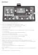
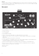


Front Panel
Gain dial: selects the gain of the input in stepped values of 0
Trim dial: allows an additional 0dB of gain to be applied to a mic or line signal
Activates a gain range of 0-60dB across the stepped Gain dial (the default is 0-0dB)
Phantom Power switch: supplies +8V to the MIC input on the rear panel
Inverts the phase of the signal
Activates a high-pass lter
Allows the signal to be sent to additional processors (via the send and return on the rear panel) before converting to digital
Selects the type of input
Sets the Mic input impedance to 600Ω (Low), kΩ (ISA 0), kΩ (Med) or 6k8Ω (High)
Sets the instrument input impedance to 70kΩ or .MΩ
Instrument Gain Dial: sets the gain of the instrument (connected to DI) to between 0 and 0dB
Allow an instrument to be connected directly (DI) and then sent back to an amp (Amp)
Allows calibration of the VU meter using the rear panel dial
Moving-coil VU meter: displays the average level of the main input signal
Displays the input signal after the insert (return signal) on the VU meter and the rst peak meter when pressed
Peak LED meters: show the main input (left meter) and either the instrument input (DI) or the EXT IP levels (right meter). These
are the inputs into the optional ADC
TRS socket for connecting headphones
Gain dial for any connected headphones
Sends the cue mix, connected to the rear panel inputs, to the headphones when active
Selects the sample rate
Selects the ADC to lock to an external source connected to the word clock input on the rear panel (either standard word clock or
56x)
Lock LED indicates when a successful synchronisation is achieved
.
.
.
.
5.
6.
7.
8.
.
0.
.
.
.
.
5.
6.
7.
8.
.
0.
.
.
1 2
3 4 5 6 7
8 9 10 11 12
13
14
15
16
17 18 19
20
21
22