
User Guide


6
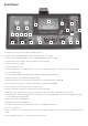
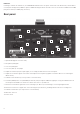
Phase
Pressing PHASE inverts the phase of the selected input to correct phase problems when using multiple microphones, or when
incorrect wiring polarity has occurred.
Insert
Activating the INSERT switch (illuminated when active) breaks the signal path of the channel, so that the signal sent to the rst ADC
Input and the analogue output on the rear panel is the signal received at the INSERT RETURN connector (on the rear panel) rather
than the direct mic, line or instrument signal. This switch is designed to allow the input signal to be routed to other hardware for
processing and then back into the ISA One for digital conversion. The POST INSERT switch on the front panel allows the ‘return’
signal level to be viewed on the left-hand LED peak meter before conversion (see the Metering section on the next page for details).
HPF
Pressing the HPF switch makes the High Pass Filter active in the audio path. This is useful for removing any unwanted bass caused
by proximity effect or rumble. The lter provides a 75Hz knee frequency with 8dB/octave roll-off.
Z In (Input Impedance)
Pressing the Z In switch steps through each of the four transformer preamp input impedance values, as indicated by the
corresponding LEDs. By selecting different values for the impedance of the ISA One transformer input, the performance of both
the ISA One preamp and the microphone connected can be tailored to set the desired level and frequency response. The impedance
values are as follows:
Low – 600Ω, ISA 0 – kΩ, Med – kΩ, High – 6k8 Ω
A guide to setting input impedance is available in the Applications section.
Instrument input impedance
The Instrument Z In switch toggles between High and Low impedance settings for the instrument input. (These settings have the
same effect on signal level and frequency response as outlined in the input impedance explanation in the Applications section.) The
impedance values are as follows:
Low – 70kΩ, High – .MΩ
Instrument i/o (DI and AMP)
The two connectors in the Instrument section on the front panel, labelled DI and Amp, are for connecting a guitar or bass directly
and then sending back to an amplier. The left unbalanced/TS connector (DI) is therefore an input for receiving the direct guitar
signal, whilst the right unbalanced/TS connector (Amp) is an output for linking back to a guitar amp. The rear panel DI OUT
connector can then feed the instrument signal to an external recording medium or audio interface. This facility can be used even
if a microphone or line-level signal is being recorded simultaneously (see the Two-channel Recording Options for details). See the
Recording an Instrument section for more details about using a guitar with ISA One.
Phones
The socket labelled phones allows a pair of headphones with a TRS ¼” Jack plug to be connected to ISA One. When in the default
state (the CUE MIX button is not lit), the signal received in the headphones is the input or inputs connected to ISA One. This will
normally be simply a mic, line or instrument signal selected by the INPUT switch. However, in a situation where an instrument and
a mic or line are in use, or a mic/line and an external signal (connected to the rear panel), a non-adjustable mix of all inputs will be
heard. For more information on two-channel recording and monitoring options, see the Applications section.
With the CUE MIX button active, the signal sent to the headphones is the one received at the CUE MIX INPUTS on the rear panel. See
the next section for details.
The Volume dial to the right can be used to set the level of the signal in the headphones, once the relevant source is selected.